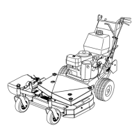
Figure11
1.Axlepivotbolt2.Axleadjustmentbolt
4.Placeajackundertherearcenteroftheengine
frame.Raisethebackendoftheengineframeup
enoughtoremovethefront2axleadjustmentbolts
(Figure11).
Note:Usejackstandstosupportthemachine.
5.Raiseorlowertheengineframewiththejackso
thatyoucaninstallthefront2axleadjustmentbolts
inthedesiredholelocation(Figure11).
Note:Useataperedpunchtohelpaligntheholes.
6.Tightenall4boltsandlowerthemower.
7.Adjustthecontrolrodsandthebrakelinkages
asrequired.RefertoServicingtheBrakesand
AdjustingtheControlRods.
Important:Youmustadjustthecontrolrods
andthebrakelinkagewhenyouchangethe
axlepositionsforpropertractionandbrake
function.
AdjustingtheCasterPosition
1.UsingtheHeight-of-CutChart,adjustthecaster
spacerstomatchwiththeaxleholeselected
(Figure12).
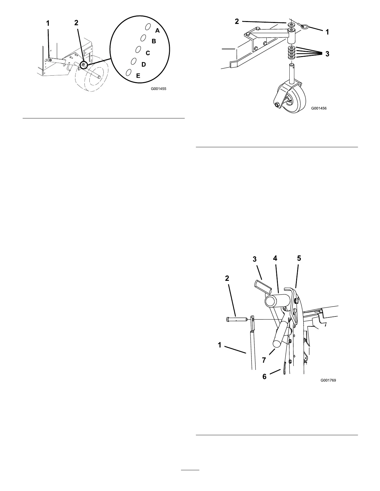
Figure12
1.Latchpin
3.Spacer,1/2inch(13mm)
2.Spacer,3/16inch(5mm)
2.Removethelatchpin,slidethecasterfromthe
support,andchangethespacers(Figure12).
3.Installthecasterinthesupportandinsertthelatch
pin(Figure12).
AdjustingtheHandleHeight
Thehandlepositioncanbeadjustedtomatchthe
operator’sheightpreference.
1.Removethehairpincotterpinsandclevispinsfrom
thedriveleversandneutrallocks(Figure13).
Figure13
1.Controlrod
5.Neutrallock
2.Clevispin
6.Hairpincotterpin
3.OperatorPresence
Controllever(OPC)
7.Lefthandleshown
4.Handle8.Drivelever
2.Loosentheupperbolts(3/8x1-1/4inches)and
angenutsecuringhandletorearframe(Figure14).
17