3.Removethelowerbolts(3/8x1inch)andange
nutssecuringhandletorearframe(Figure14).
4.Pivotthehandletothedesiredoperatingposition
andinstallthelowerangebolts(3/8x1inch)and
angenutsintothemountingholes.Tightenall
angebolts.
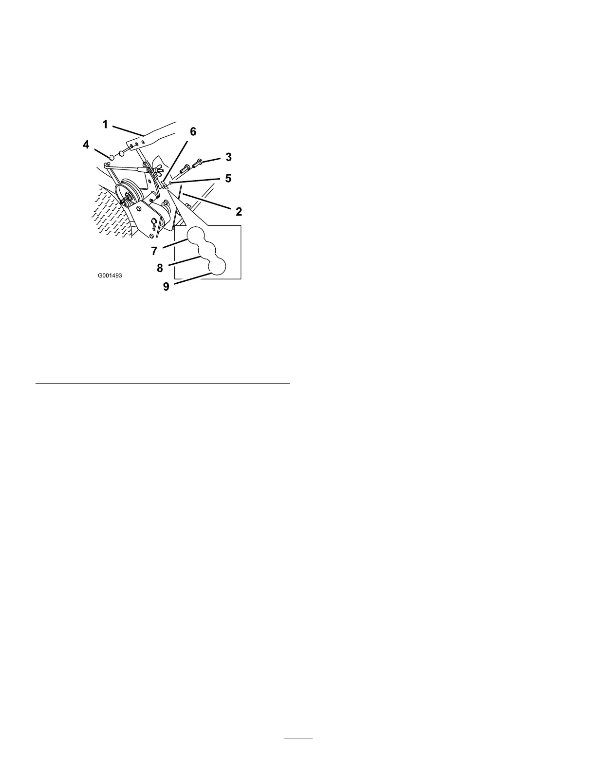
Figure14
1.Upperhandle6.Lowermountingholes
2.Rearframe
7.Lowposition
3.Flangebolt(3/8x1inch)
8.Middleposition
4.Locknut(3/8inch)
9.Highposition
5.Uppermountinghole
5.Adjustthecontrolrodlengthbyrotatingthecontrol
rodintherodtting(Figure13).
6.Installahairpincotterbetweenthedriveleversand
neutrallocksandintotheclevispins(Figure13).
Note:Makesuretheclevispinsareinsertedinto
theneutrallocks.
7.Checktheparkingbrakeadjustment.Referto
CheckingtheBrakesinBrakeMaintenance.
18