Cooling System
Maintenance
Cleaning the Cooling System
Clean the air intak e screen from g rass and debris before
eac h use .
Clean the cooling fins and engine shrouds ev er y 100
hours .
1. Diseng ag e the PTO , set the parking brak e , stop the
engine , and remo v e the k ey .
2. R emo v e the air intak e screen, cylinder co v ers , and
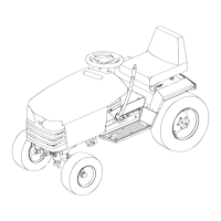
fan housing ( Figure 50 ).
Figure 50
1. Air intake screen 3. Cylinder cover
2. Fan housing 4. Cylinder cover
3. Clean debris and g rass from the par ts .
4. Install the air intak e screen, cylinder co v ers , and
fan housing .
Brake Maintenance
Servicing the Brake
Alw a ys set the parking brak e when y ou stop the
mac hine or lea v e it unattended. If the parking brak e
does not hold securely , an adjustment is required.
Checking the Brake
1. P ark the mac hine on a lev el surface , diseng ag e the
PTO , and set the parking brak e .
2. Stop the engine , remo v e the k ey , and w ait for all
mo ving par ts to stop before lea ving the operating
position.
3. R ear wheels m ust loc k and skid when y ou tr y to
push the tractor forw ard. Adjustment is required if
the wheels tur n and do not loc k; refer to Adjusting
the Brak e .
4. R elease the brak e and mo v e the dri v e control rod
to the push position; refer to Pushing the Mac hine
b y Hand in Operation , pag e 19 . W heels should
rotate freely .
5. If both conditions are met no adjustment is
required.
Adjusting the Brake
1. Chec k the brak e before y ou adjust it; refer to
Chec king the Brak e .
2. R elease the parking brak e; refer to R eleasing the
P arking Brak e in Operation , pag e 19
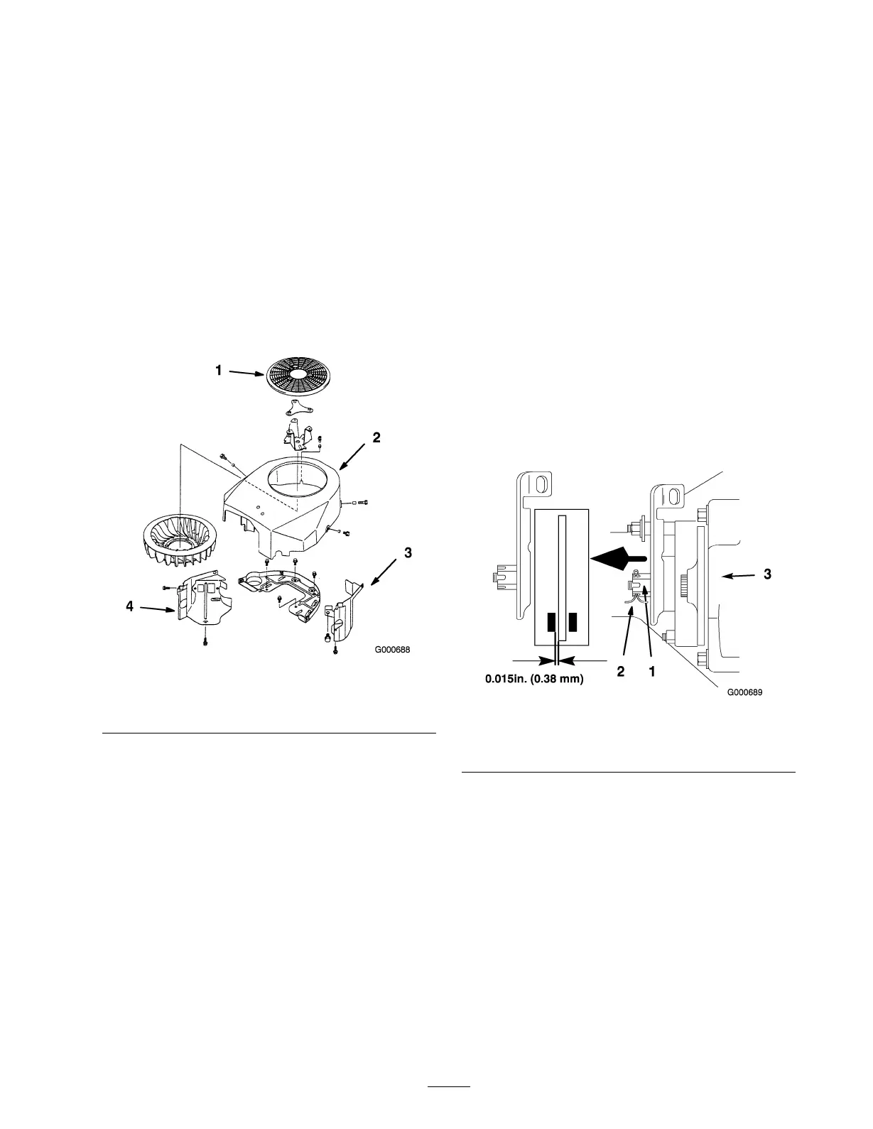
3. T o adjust the brak e remo v e the cotter pin and
loosen the brak e adjusting n ut slightly ( Figure 51 ).
Figure 51
1. Brake adjusting nut 3. Right Front of Transaxle
2. Cotter pin
4. Carefully inser t a 0.015 inc h (0.38 mm) feeler
g aug e betw een the outer brak e pad and rotor disk
( Figure 51 ).
5. Tighten the brak e adjusting n ut until slight
resistance is felt on the feeler g aug e when sliding it
in and out. Install the cotter pin.
6. Chec k the brak e operation ag ain; refer to Chec king
the Brak e .
Important: W ith the par king brak e r eleased,
the r ear wheels must r otate fr eel y when y ou
push the mo w er . If the 0.015 inch (0.38 mm)
clearance and fr ee wheel r otation cannot
be achiev ed contact y our ser vice dealer
immediatel y .
37