Secure seat suspension to seat mounting plate
with (4) flange locknuts (Fig. 6 & 7).
(&2/%
%!1 020.%,0(-,
Mount seat to seat suspension with (4) capscrews,
lockwashers and flatwashers (Fig. 6 & 7).
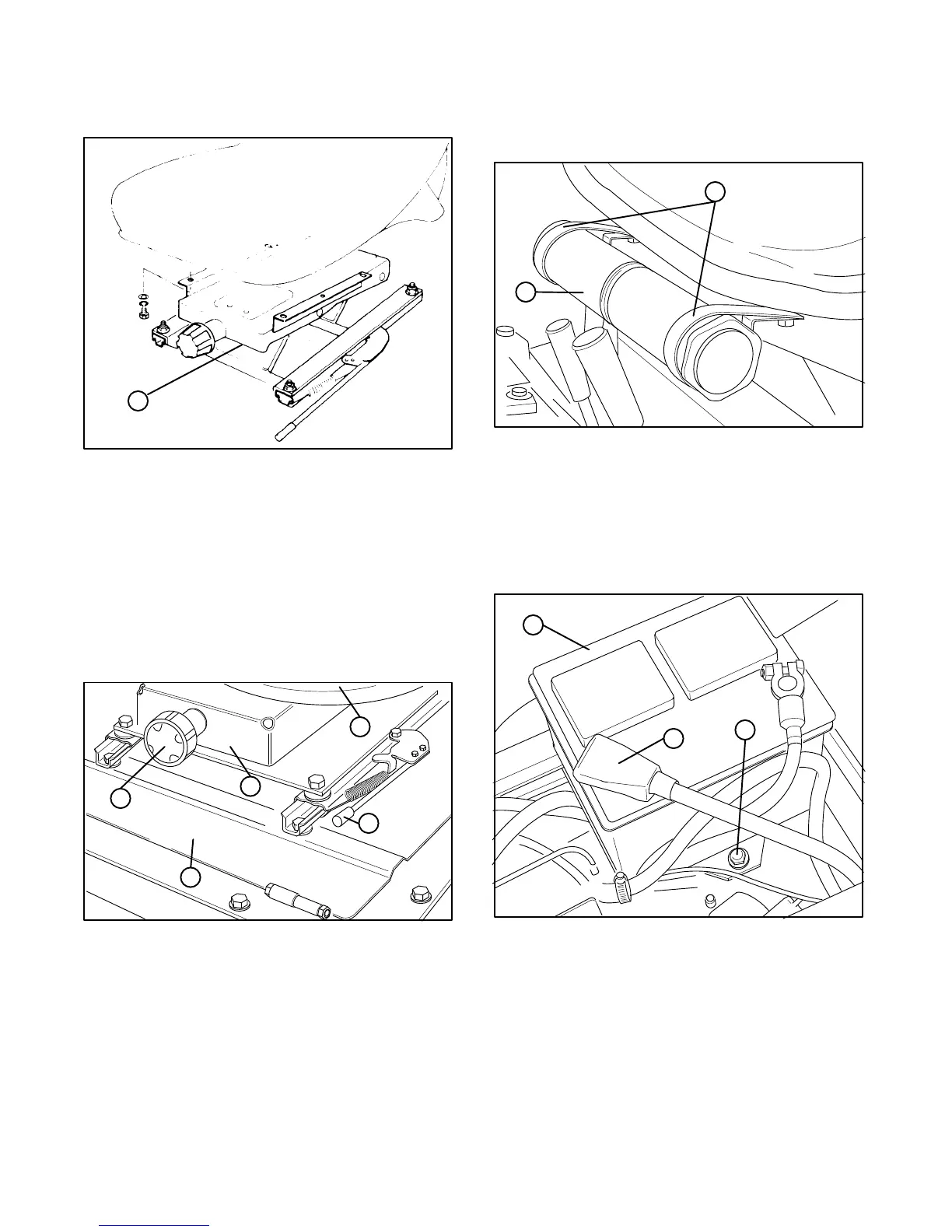
Adjust seat for operator's comfort and weight. To
adjust seat fore and aft, pull handle on left side of seat
assembly outward (Fig. 7). Release handle to lock seat
position. To adjust for operator's weight, turn spring
tension knob; clockwise to increase tension,
counterclockwise to decrease spring tension (Fig. 7).
(&2/%
%!1
20.%,0(-, !00%+"*4
-2,1(,& .*!1%
-/3!/$"!#)3!/$ '!,$*%
./(,& 1%,0(-, ),-"
Remove manual tube and R-clamps secured to
seat plate. Retain (2) mounting capscrews and
flatwashers.
Loosely mount R-clamps to outer holes in right
side of seat with (2) capscrews and flatwashers
previously removed. (Fig. 8).
Install manual tube into R-clamps, insert manual
into tube and thread cap into tube (Fig. 2). Tighten
capscrews.
(&2/%
!,2!* 12"%
#*!+.0
LIft engine cover. Check to see that the battery is
securely fastened in place (Fig. 9).
(&2/%
!11%/4
!11%/4 0%#2/(,& "-*1
2""%/ "--1
Check battery charge with a hydrometer. If battery
needs charging, be sure at least one of the battery
cable is disconnected from the battery before the
charger is connected.
Remove tape from battery cables and secure the
cables to the proper battery post. The positive (+) red
cable goes to the positive post and the negative (-)
black cable goes to the negative post on the battery.

 Loading...


