!
! "! " !!
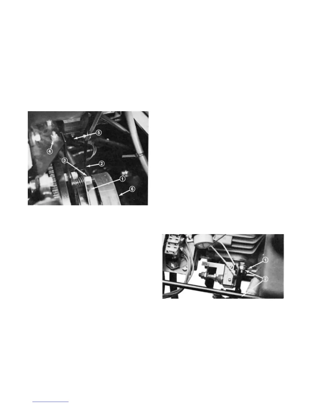
The power take off electric clutch can be adjusted by
following the following procedure:
Turn engine off and remove the ignition key. Set the
parking brake. Raise the engine hood and allow the
engine to cool.
Remove the left hand clutch retainer bracket nut
and bolt so that the retainer bracket rubber bumper
can be removed (Fig. 39).
,*74(
/76&+
$,4 *$3
'-756,1* 176
()6 4(6$,1(4 %4$&.(6 176 %2/6
/(&64,&$/ &211(&624
! %(/6
Unplug clutch electric connector (Fig. 39).
Adjust the air gap so that a .015 inch feeler gauge
slides in between the clutch lining and friction plate with
light pressure (Fig. 39). The gap can be decreased by
turning the adjusting nut clockwise (Fig. 38).
Rotate the clutch by hand and adjust all three air
gaps. After all three gaps have been set, check all three
again. Adjusting one gap can alter the other gaps.
Reinstall the bracket and retaining nut and bolt.
Reconnect the clutch electrical connector.
!
# !
The cooling system must be filled with a 50/50 solution
of water and permanent ethylene glycol antiĆfreeze.
After every two years, drain the coolant from the
radiator, reservoir expansion tank and engine by
opening the drain cock and block plug. After coolant is
drained, flush the entire system and refill it with a 50/50
solution of water and antiĆfreeze. Capacity of cooling
system is approximately 7 quarts (6.4 l). When filling, fill
the radiator completely and fill the expansion tank to
between the marks. DO NOT OVERFILL. Always install
radiator cap securely.
" ! !
"!
The machine must not creep when traction pedal is
released. If it does creep, an adjustment is required.
Park machine on a level surface and shut engine
off. Depress only the right brake pedal and engage the
parking brake.
Jack up left front side of machine until tire is off
shop floor. Support machine with jack stands to
prevent it from falling accidentally.
Lift seat. Visually inspect traction linkage for
possible binding condition, correct if necessary and
check machine operation. if condition still exists,
repeat steps 1 and 2 and proceed to step 4.
Loosen two locknut securing pump plate so plate
is free to move (Fig. 40).
Start engine and rotate pump plate (Fig. 40) in
either direction until wheel ceases rotation.
,*74(
703 3/$6( 2&.176
Stop engine and tighten locknuts to secure pump
plate (Fig. 40).
Start engine and check adjustment. Repeat
adjustment, if necessary.
Stop the engine and release right brake. Remove
jack stands and lower machine to the shop floor. Test
drive the machine to be sure it does not creep.

 Loading...


