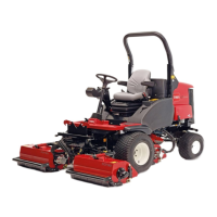
g004653
Figure24
1.Cuttingedge3.Wear/slotforming
2.Sailarea4.Crack
CheckingforBentBlades
1.DisengagethePTO,releasethetractionpedal
andsettheparkingbrake.
2.MovethethrottlelevertotheSlowposition,
stoptheengine,removethekey,andwaitfor
allmovingpartstostopbeforeleavingthe
operatingposition.
3.Rotatethebladesuntiltheendsfaceforward
andbackward(Figure25).
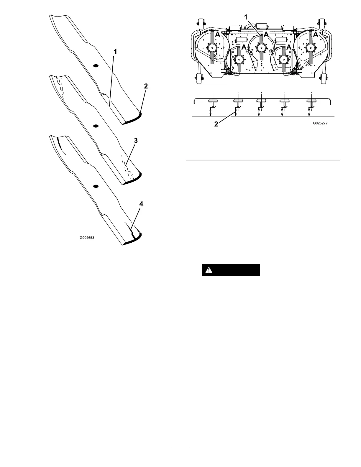
g025277
Figure25
1.PositionA
2.Measureherefromblade
tohardsurface
4.Measurefromalevelsurfacetothecutting
edge,positionA,oftheblades(Figure25).Note
thisdimension.
5.Rotatetheoppositeendsofthebladesforward.
6.Measurefromalevelsurfacetothecuttingedge
ofthebladesatthesamepositionasinstep3
above.Thedifferencebetweenthedimensions
obtainedinsteps3and4mustnotexceed
3mm(1/8inch).Ifthisdimensionexceeds
3mm(1/8inch),thebladeisbentandmustbe
replaced;refertoRemovingtheBlades(page
20)andInstallingtheBlades(page21).
WARNING
Abladethatisbentordamagedcould
breakapartandcouldseriouslyinjureor
killyouorbystanders.
•Alwaysreplacebentordamaged
bladewithanewblade.
•Neverleorcreatesharpnotchesin
theedgesorsurfacesofblade.
RemovingtheBlades
Bladesmustbereplacedifasolidobjectishit,ifthe
bladeisoutofbalanceorisbent.Toensureoptimum
performanceandcontinuedsafetyconformanceof
themachine,usegenuineT ororeplacementblades.
Replacementbladesmadebyothermanufacturers
mayresultinnon-conformancewithsafetystandards.
20

 Loading...