PIVOTING ZONE START BRAKE
48
There are two versions of this brake. The function is
the same, but they contact different parts of the
flywheel. Fi
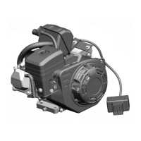
ure 88 is a dia
ram of the system used on
recoil start en
ines. The brake pad en
a
es the
bottom of the flywheel. Fi
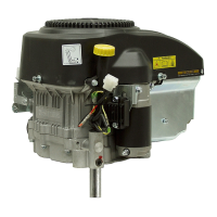
ure 89 is a photo of a
sli
htly different system used on electric start en
ines.
On electric start en
ines, the brake pad must contact
the side of the flywheel to clear the teeth of the flywheel
rin
ear.
Disassembly
Figure 88
3297-023
Figure 89
0893-040
Note: Numbers in parentheses in the followin
procedures refer to the previous illustration (see Fi
ure
88).
1. If the en
ine and blade are takin
more than 3
seconds to stop when the blade control bail is
released, inspect the brake pad for excessive wear
and replace if necessary. Note that the brake pad
and the brake plate are replaceable only as an
assembly.
2. To reduce the pressure of the sprin
between
brake mountin
plate (10) and brake plate (8),
squeeze tabs of brake cable that hold it in place at
the brake mountin
plate. Push cable throu
h the
hole in brake mountin
plate.
3. Slide cable out throu
h horizontal slot in brake
mountin
plate. Also, slide the ball end of the
cable up throu
h the vertical slot in the brake plate.
Note: In step 4, some units may use a 3/8" head
with 1/4" diameter screw (rather than a 10 mm).
4. Remove the 10 mm shoulder screw (7) to remove
the brake plate and brake pad attached to it.
5. If the
round strap or any part of this assembly
requires replacement, remove the second screw
(9) to remove the brake mountin
plate from the
en
ine.
1 - Ground strap stop
2 - Self-tappin
screw
3 - Brake switch lead
wire
4 - Ground strap
5 - Insulation strap
6 - Plastic rivet
(self expandin
) (2)
7 - Shoulder screw
(10 mm)
8 - Brake plate assembly
9-Screw
10 - Brake mountin
plate
Recoil
Electric Start

 Loading...
