3.LoosenthecenteringboltsinthefrontA-arm
(Figure42).
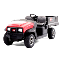
4.Removetherideheightadjustmentbolt(Figure42).
Figure42
1.Travellimitingbolt3.Rideheightadjustment
bolt
2.Centeringbolt
5.RotatethefrontA-armtothedesiredposition
(refertothenotebelow)andreplacetherideheight
adjustmentbolt(Figure42).
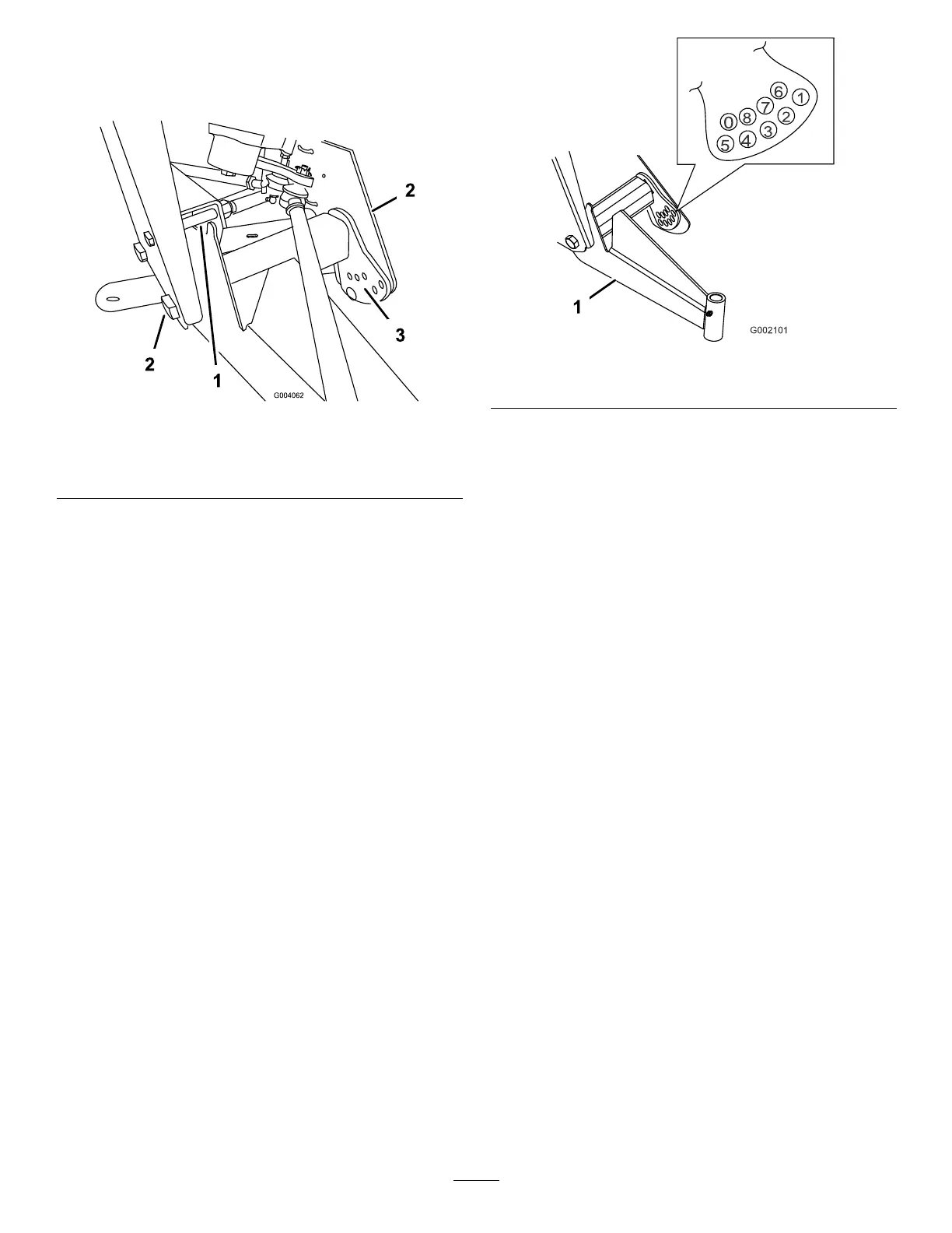
Note:TheA-armsaremadewithrubberandhave
differentspringrates.Becauseofthedifferentspring
rates,theA-armscomeadjustedfromthefactory
basedonthatspringrate.Generallytheadjustment
boltswillbeinstalledinholenumber2,3,or4
(Figure43)anditmaybedifferentfromtheleftside
(driverside)totherightside(passengerside).Ifthe
A-armslookliketheyaresagging,thentheyshould
beadjustedtothenexthighernumber(Figure43).
Eachholeequalsabout3/4inch(19mm)of
adjustmentatthewheel.Youwillalsoneedtodo
thisifyouareaddingheavyattachmentsorcarrying
heavyloadsoften.
Figure43
1.Left-handA-arm
6.Torquetherideheightadjustmentboltto
135-165ft-lb(183-224N-m).
7.Replacethetravellimitingbolt(Figure42).
Note:Thevehiclemayneedtobeloweredtothe
groundonthatsidetoinstallthebolt.
8.Tightenandtorquethecenteringboltsto
240-290ft-lb(325-393N-m).
9.Checktherideheightatthefronttongueperthe
dimensionsandparametersgivenatthebeginningof
thisprocedure.
AdjustingFrontWheelToe-In
Checkthefrontwheeltoe-inafterevery100operating
hours,orannually,whicheveroccursrst.
Thetoe-inshouldbe1/8-5/8inch(3-16mm)withthe
followingparameters:
•Thetirepressureshouldbeat12psi(83kPa).
•Therideheightshouldbecorrectbeforesettingthe
toe-in;refertoAdjustingtheFrontSuspension.
•Thevehicleshouldbedrivenbackandforthafew
timestorelaxtheA-arms.
•Measurethetoe-inwiththewheelsfacingstraight
aheadanda175-225lb(79-102kg)operatorinthe
driver’sseat.
Note:Thedrivershoulddriveuptothe
measurementareaandstayseatedinthevehicle
whilethemeasurementisbeingtaken.
Ifthevehiclewillberunwithmediumtoheavyloads
mostofthetime,setthetoe-inonthehighsideof
therecommendedamount.Ifitisgoingtoberun
35