E6581697
F-44
6
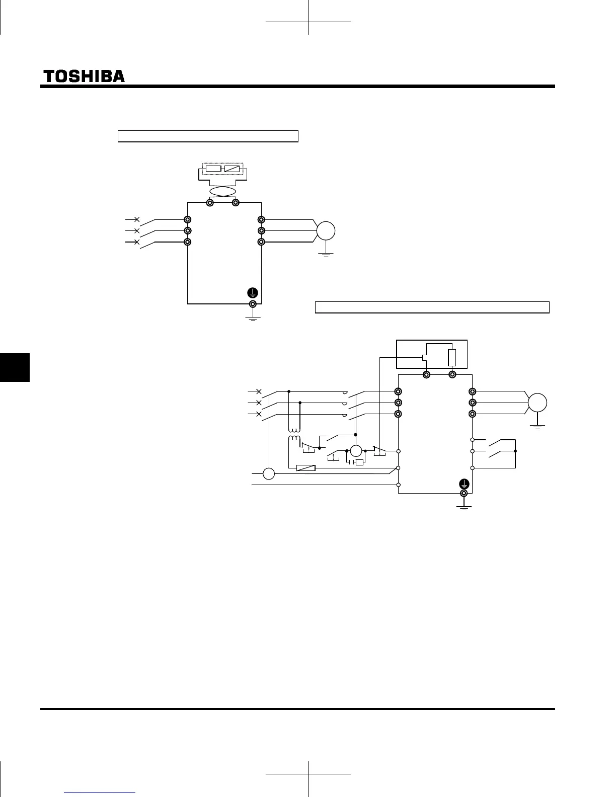
1) Connecting an external braking resistor (optional)
Separate-optional resistor (with thermal fuse)
Note 1: A TC (Trip coil) is connected, as shown in this figure, when an MCCB with a trip coil is used instead
of an MC. A step-down transformer is needed for every 500V-class inverter, but not for any 240V-
class inverter.
Note 2: As a last resort to prevent fire, be sure to connect a thermal relay (THR). Although the inverter has a
means of preventing overload and overcurrent to protect the braking resistor, the thermal relay is
activated in case the protection function fails to work. Select and connect a thermal relay (THR)
appropriate to the capacity (wattage) of the braking resistor.
Connecting thermal relays and an external braking resistor
IM
Motor
R/L1
S/L2
T/L3
U/T1
V/T2
W/T3
Three-phase main circuits
Power supply
PBe
PB
MCCB
Braking resistor (optional)
PBR
Inverter
Fuse
TC
FLB
F
FLC
FLA
R
CC
MC
Power supply
TH-R
urge
suppressor
Forward
Reverse
IM
Motor
R/L1
S/L2
T/L3
U/T1
V/T2
W/T3
Three-phase main circuits
Power supply
PBe
PB
MCCB
Braking resistor (optional)
PBR
Inverter
Step-down
transformer
2:1
MC
 Loading...