E6581697
G-3
7
Note 1) Multiple functions assigned to a single terminal operate simultaneously.
Note 2) In case of setting always active function, assign the menu number to , and (always
active function selection).
Note 3) In case of using terminal S2 as a logic input, set the parameter =0 (logic input).
Note 4) In case of using terminal S3 as a logic input, set the slide switch SW2 to LOGIC side and the parameter
=0 (logic input).
Note 5) In case of using terminal VIB as a logic input, set the parameter =1 to 4 (logic input).
Note 6) In case of using terminal VIA as a logic input, set the parameter =3 or 4 (logic input).
Note 7) When stable operation cannot be attained because of frequency setting circuit noise, increase .
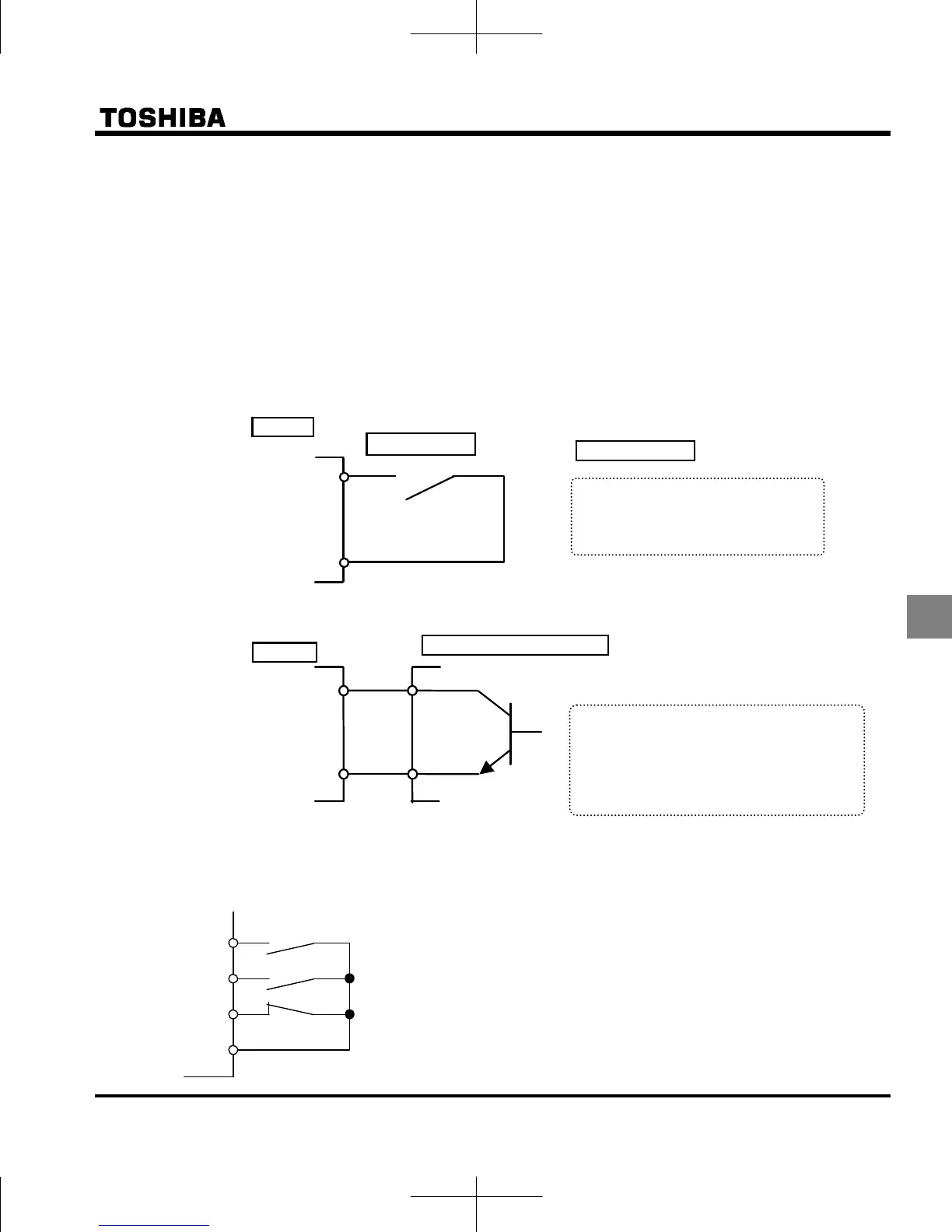
Connecting
1) For logic input
2) For connection (sink logic) via transistor output
Usage example ··· 3-wire operation (one-push operation)
Use the 3-wire operation function to operate the inverter, maintaining operation without using the sequence circuit
by inputting an external signal (reset logic signal).
F
CC
S2
Forward run
Reverse run
HD
R
Forward run (F) : Pressing forward run (F) rotates forward at
the specified frequency command value.
Reverse run (R) : Pressing reverse run (R) rotates in reverse
at the specified frequency command value.
HD (S2): Pressing HD (S2) decelerates and stops.
CC
Input terminal
Operates by short circuiting between
the input terminal and CC (common).
Use for forward rotation, reverse
rotation, and multi-stage speed.
nver
e
Relay a-contact
With sink settings
Control by connecting the input terminal
and CC (common) to the output (non-logic
switch) of the programmable controller.
Use for forward rotation, reverse rotation,
and multi-stage speed. Use a 5 mA
transistor that operates at 24 V dc.
Inverter
Programmable controller
CC
Input terminal
 Loading...


