E6581697
G-15
7
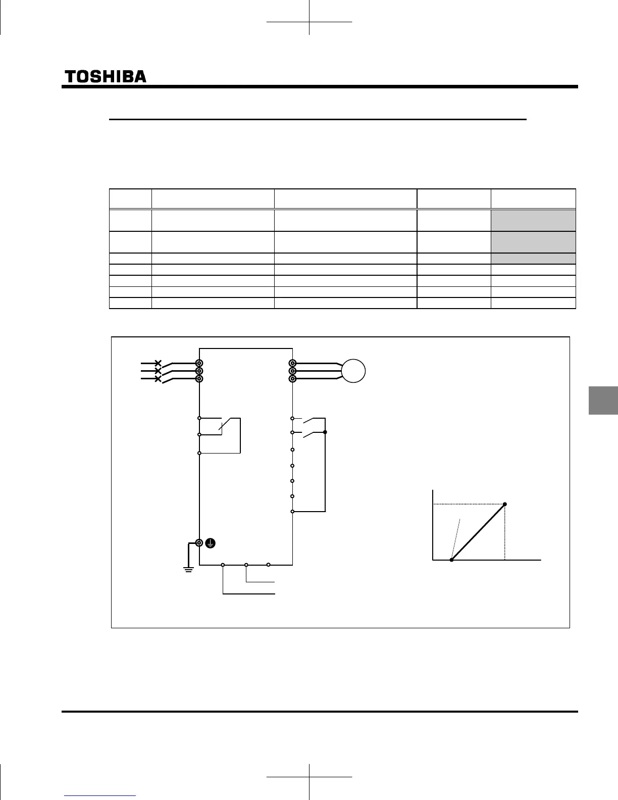
7.3.2 Settings depending on current (4 to 20 mA) input
You can set the frequency settings by inputting an analog current signal of 4 (0) to 20mA dc between the VIC and
CC terminals.
The following shows examples when the run command is input from the terminal.
Title Function Adjustment range Default setting Setting example
Command mode selection 0 – 4
1
(panel keypad)
0
(terminal board)
Frequency setting mode
selection
0 – 11
0
(setting dial 1)
8
(terminal board VIC)
VIC input point 1 setting 0 – 100% 0 20 (or 0)
VIC input point 1 frequency 0.0 - 500.0Hz 0.0 0.0
VIC input point 2 setting 0 – 100% 100 100
VIC input point 2 frequency 0.0 - 500.0Hz *1 50.0/60.0
Analog input filter 2 - 1000 ms 64 64
*1: Default setting values vary depending on the setup menu setting. Refer to section 11.5.
Hz
%
Point 2
Point 1
Frequency setting signal
0% 20% 100%
(0mA) (4mA) (20 mA)
Current input
Operation frequency
Run and stop settings
You can switch between forward run (F) and
reverser run (R), and run/stop with external
signals.
Setting characteristics for the frequency
setting signal and operation frequency
Set characteristics at two points in the
diagram below.
Connecting and calibrating the frequency
meter
Select the type of meter connected at
and calibrate.
Refer to section 3.4 for details.
Motor
IM
R/L1
U/T1
MCCB
Power
Supply
S/L2
T/L3
V/T2
W/T3
CC
FLC
VIC PP
VF-MB1
+
-
* Connect a single-phase
input model to R/L1 and
S/L2/N.
4 (0) to 20 mA dc
FLA
FLB
Forward
run
Reverse
un
CC
F
R
S1
S2
S3
RES
 Loading...


