E6581697
H-5
8
MODE
(Continued)
Item displayed
Panel
operated
LED display Description
Input voltage
The inverter input voltage (DC detection) when the trip
occurred is displayed. (%/V).
Output voltage
The inverter output voltage when the trip occurred is
displayed. (%/V)
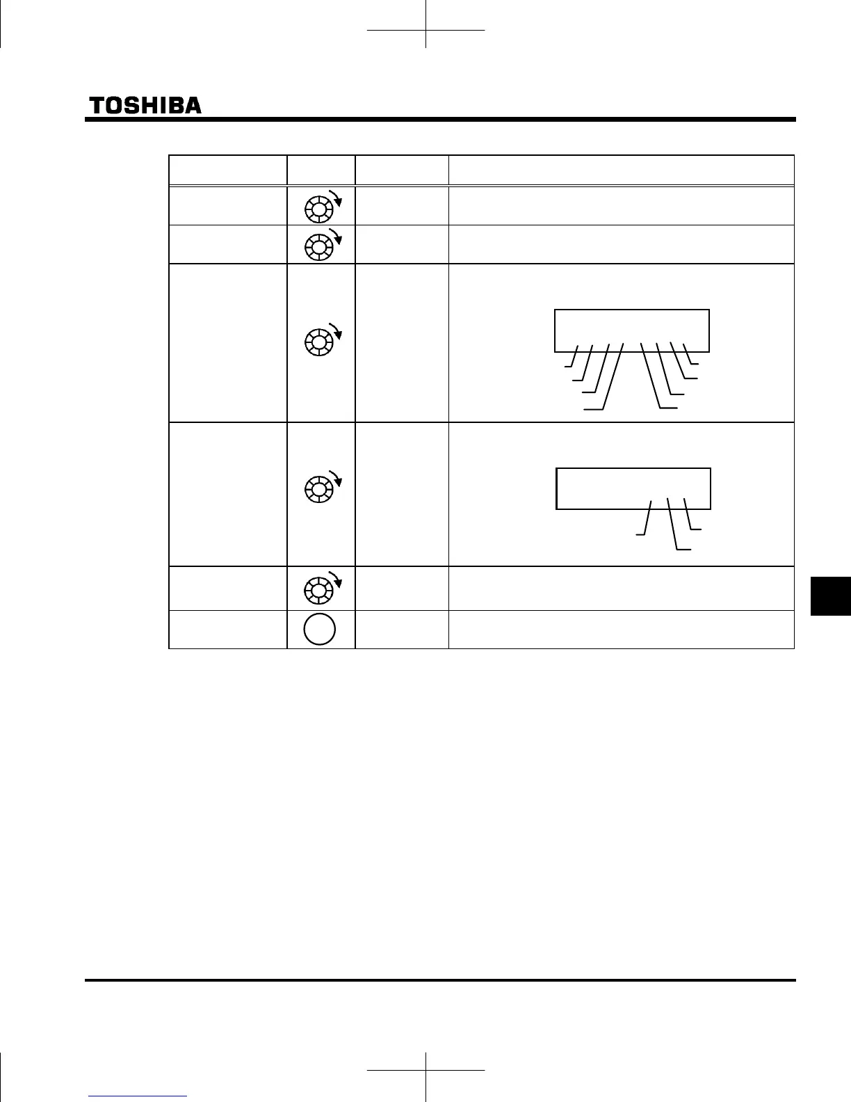
Input terminal
}}i}}i}i
The ON/OFF status of each of the control signal input
terminals (F, R, RES, S1, S2, S3, VIB, VIA) are displayed in
bits.
ON:
OFF:
Output terminal
0 }ii
The ON/OFF status of each of the control signal output
terminals (RY-RC, OUT, FL) are displayed in bits.
ON:
OFF:
Cumulative
operation time
The cumulative operation time when the trip occurred is
displayed.
(0.1=10 hours, 1.00=100 hours)
Past trip 1
Press this key to return to past trip 1.
* The monitor value of a trip is not always recorded as the maximum value because of the time required for
detection.
Refer to page H-8 for notes.
Note 3
Note 4
}}i}}i}i
VIA
S3
F
R
S2
VIB
S1
RES
Note 5
Note 9
0 }ii
FL
RY-RC
OUT
 Loading...


