E6581697
A-19
1
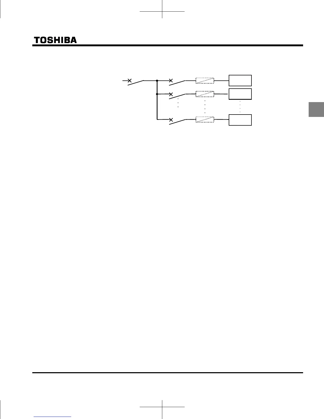
Circuit breaking when two or more inverters are used on the same power line
MCCB1
MCCBn
1
MCCB3
MCCB2
INV1
INV2
INVn
(circuit breaking fuse)
Breaking of selected inverter
There is no fuse in the inverter's main circuit. Thus, as the diagram above shows, when more than one
inverter is used on the same power line, you must select interrupting characteristics so that only
MCCB2 to MCCBn+1 will trip and the MCCB1 will not trip when a short occurs in the inverter (INV1).
When you cannot select the proper characteristics install a circuit interrupting fuse behind MCCB2 to
MCCBn+1.
If power supply distortion is not negligible
If the power supply distortion is not negligible because the inverter shares a power distribution line with
other systems causing distorted waves, such as systems with thyristors or large-capacity inverters,
install an input reactor to improve the input power factor, to reduce higher harmonics, or to suppress
external surges.
If multiple inverters are connected with common DC bus link
When inverters are fed by AC power supply and connected with common DC bus link, ground fault trip
protection may operate. In that case, set ground fault detection selection (
f614) to 0 “Disabled”.
Disposal
Refer to chapter 16.
MCCB:
No-fuse breaker
 Loading...


