E6581697
B-9
2
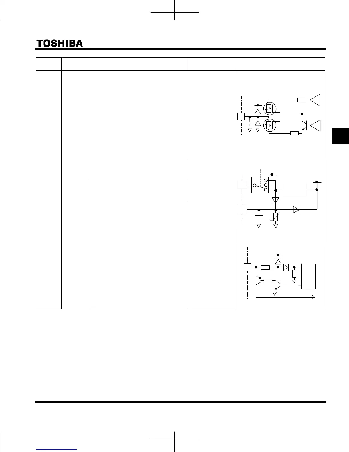
Terminal
symbol
Input /
output
Function
Electrical
specifications
Inverter internal circuits
FM Output
Multifunction programmable analog
output. Default setting: output frequency.
The function can be changed to ammeter,
0-10Vdc voltage or 0-20mAdc (4-20mA)
current output by parameter
setting.
Resolution Max. 1/1000.
1mAdc full-scale
ammeter or
QS60T(option)
0-20mA (4-20mA)
DC ammeter
Permissible load
resistance:
750Ω or less
0-10V DC volt
meter
Permissible load
resistance:
1kΩ or more
Output 24Vdc power output 24Vdc-100mA
P24
Input
This terminal can be used as a common
terminal when an external power supply
is used by changing SW1 to PLC side.
-
Input
DC power input terminal for operating the
control circuit. Connect a control power
backup device (option) between +SU and
CC.
Voltage: 24Vdc±
10%
Current: 1A or
more
+SU
Output
It is used with STO for safety function.
+SU and STO terminals are short-
circuited by metal bar at default setting.
-
STO
Note 2)
Input
When +SU and STO are short-circuited,
the inverter is put into a standby state.
(Default setting) And when the circuit
between them is opened, the motor is
coasting stop. These terminals can be
used for inter lock.
This terminal is not a multifunction
programmable input terminal.
It is a terminal with the safety function
that complies with SIL II of the safety
standard IEC61508.
Independently of
SW1
ON: DC17V or
more
OFF: Less than
DC12V
(OFF: Coast stop)
Note2) When STO terminal is used as the safety function, refer to section 9.3.
STO
27.4k
10k
+5 V
CPU
+24V
Current
limiter
+SU
U
P24
EXT
SW1
+24V
68
121
Current
+
–
Voltage
+
–
FM
+24 V
 Loading...