E6581697
B-12
2
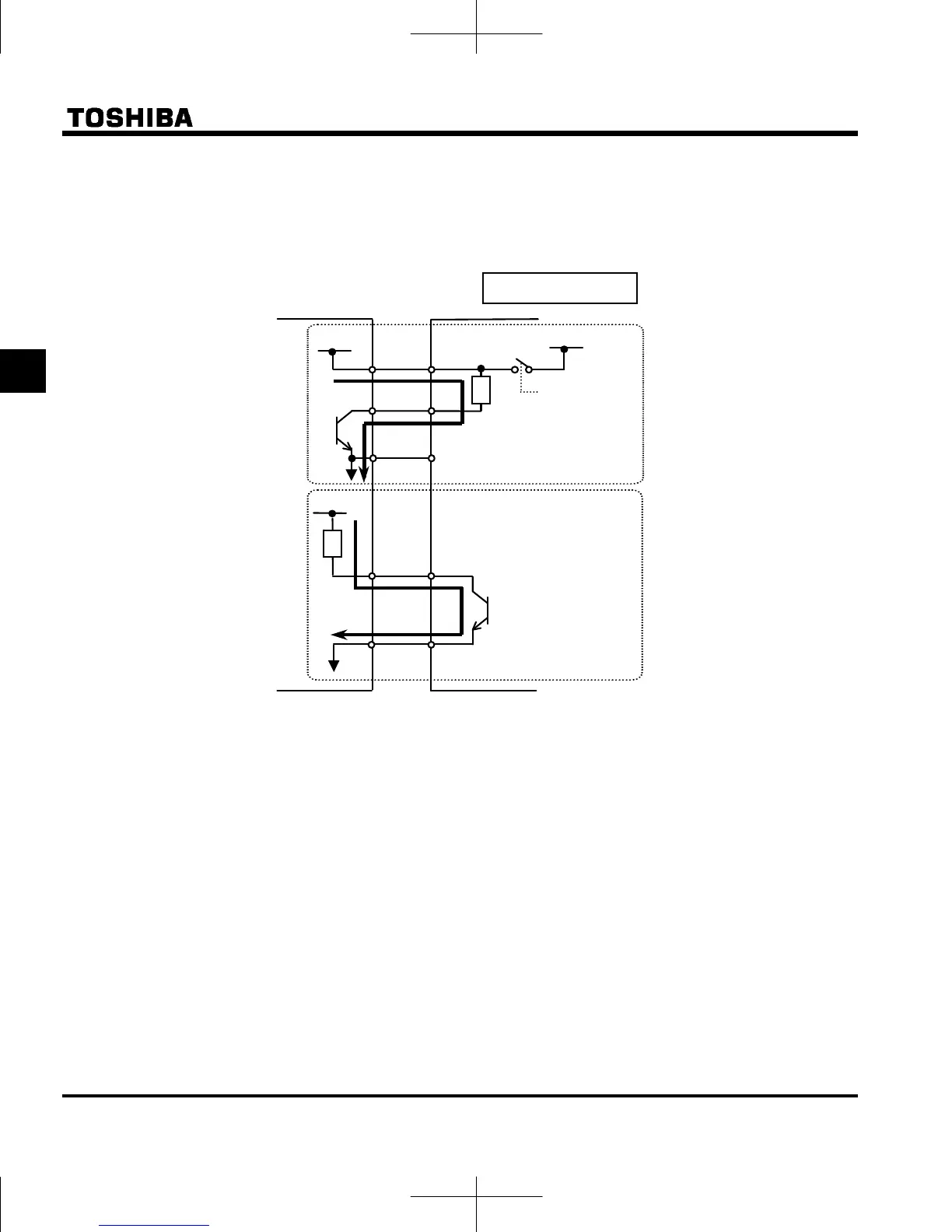
■ SINK (Negative) logic (When an external power supply is used)
The P24 terminal is used to connect to an external power supply or to separate a terminal from other input
or output terminals.
<Examples of connections when an external power supply is used>
■ Switching of slide switch
Refer to section 1.3.3 3) about location of slide switch.
(1) Switching of sink/source logic: SW1 (Default setting : PLC side)
Setting of sink/source logic for F, R, RES, S1, S2, and S3 terminals are switched by slide switch SW1.
When an external power supply is used for sink logic, set the slide switch SW1 to PLC side.
Set the sink/source logic switching before power supply switches on.
After confirming the right for sink/source setting, power supply switches on.
(2) Switching of S3 terminal function: SW2 (Default setting : LOGIC side)
Setting of logic input/ PTC input for S3 terminal is switched by slide switch SW2 and parameter 47.
When using S3 terminal as a logic input terminal, set the slide switch SW2 to LOGIC side and set the
parameter =.
When using S3 terminal as a PTC input terminal, set the slide switch SW2 to PTC side and set the
parameter =.
Match the setting of slide switch SW2 and parameter surely.
If it is not, this can result in malfunction.
Sink
Ne
ative
lo
ic
Slide switch SW1 : PLC side
F
Output
In
ut
24V
DC
Out
ut
OUT
NO
24V
DC
In
ut
Common
Inverter
Programmable
controller
P24
Common
24V
DC
SW1: PLC side
CC
 Loading...


