E6581697
C-23
3
■ =( Variable torque characteristic), = (Temperature estimation)
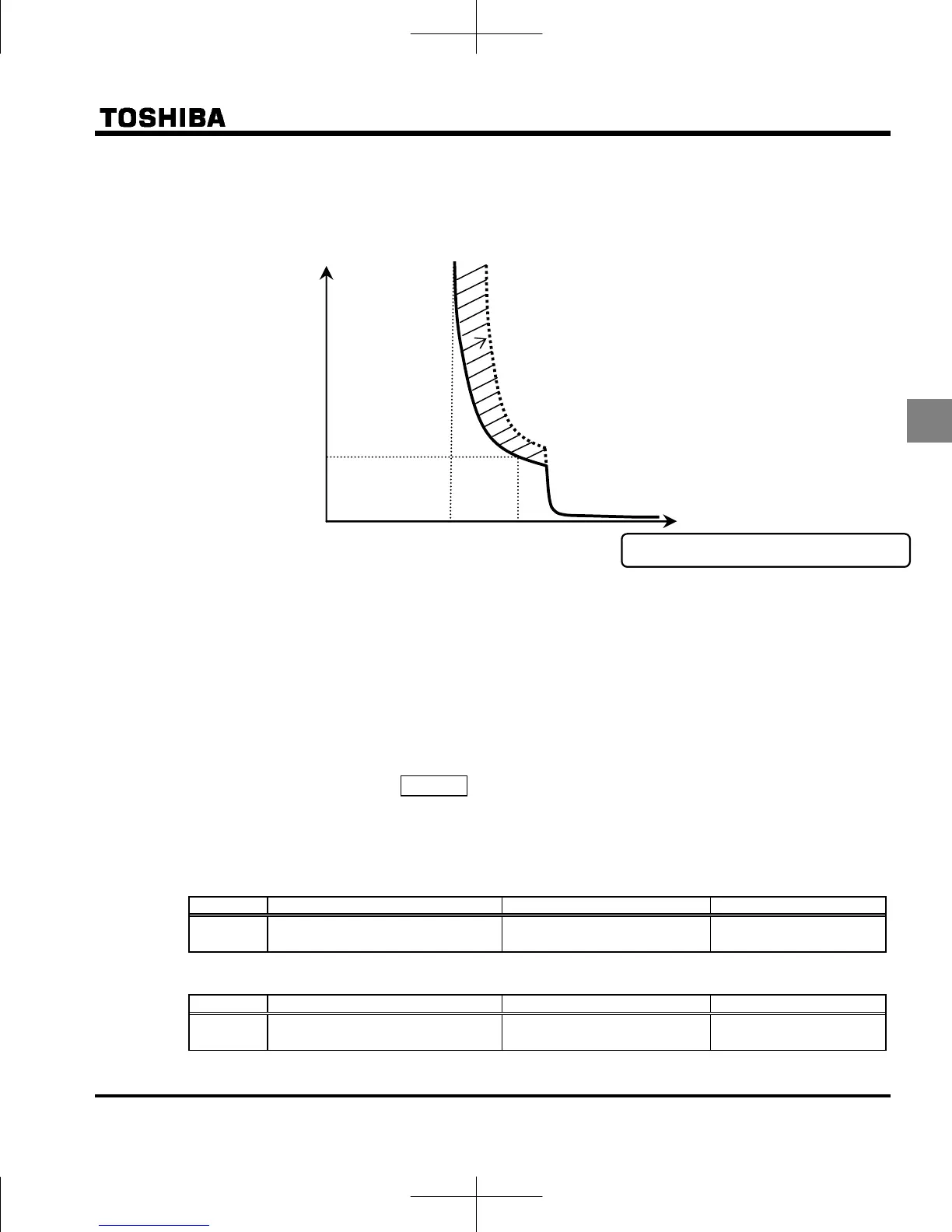
This parameter adjusts automatically overload protection, predicting the inverter internal temperature rise.
(diagonally shaded area in the figure below)
Inverter overload protection characteristics
Note 1: The rated output current of inverter is changed by setting of
aul=1 or 2.
Refer to page L-1 about each rated output current.
Note 2: Parameter
aul is displayed as “0” during reading after this is set.
Note 3: Present setting of inverter overload characteristic can be confirmed by status monitor.
Refer to monitor “Overload and region setting” of section 8.2.1.
6) Overload alarm level f657
When the motor overload level reaches to setting value (%) of overload trip (OL2) level, output
frequency monitor and “L” of left side digit are blinking on overload alarm status.
Overload alarm signal can be output.
[Parameters settings]
Title Function Adjustment range Default setting
Overload alarm level
10-100 (%)
50
[Example of setting] : Assigning the overload alarm to the OUT terminal.
Title Function Adjustment range Setting
Output terminal selection 2A (OUT)
0-255
16: POL
17 is reverse signal.
60
100%: Inverter rated out
ut current
time
s
Monitored output current [%]
0
105% 120%
 Loading...


