– 106 –
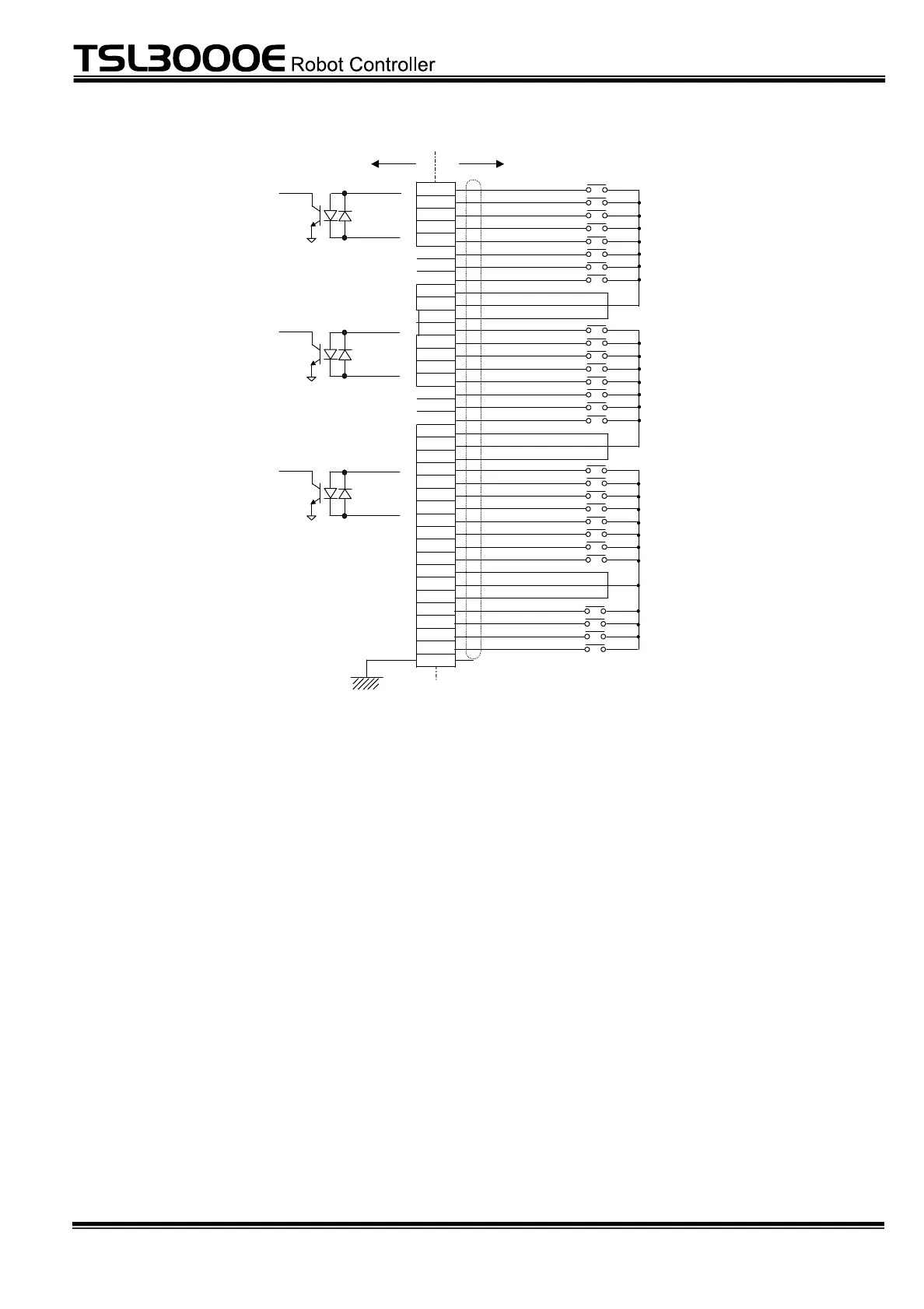
INPUT
TR48DIOCN
1
20
2
21
3
22
4
23
5
24
6
25
7
26
8
27
9
28
10
29
11
30
12
31
13
32
14
33
15
34
16
35
17
36
18
37
19
P24V
P24G
INCOM1
INCOM2
INCOM3
DI_101
to
DI_108
to
INCOM1
INCOM2
INCOM3
DI_133 DI_140
DI_109 DI_116
DI_141 DI_148
DI_117 DI_128
DI_149 DI_160
(101/133)
(102/134)
(103/135)
(104/136)
(105/137)
(106/138)
(107/139)
(108/140)
(109/141)
(110/142)
(111/143)
(112/144)
(113/145)
(114/146)
(115/147)
(116/148)
(117/149)
(118/150)
(119/151)
(120/152)
(121/153)
(122/154)
(123/155)
(124/156)
(125/157)
(126/158)
(127/159)
(128/160)
P24V
P24G
P24V
P24G
DI_101/DI_133
DI_102/DI_134
DI_103/DI_135
DI_104/DI_136
DI_105/DI_137
DI_106/DI_138
DI_108/DI_140
DI_107/DI_139
DI_109/DI_141
DI_110/DI_142
DI_111/DI_143
DI_112/DI_144
DI_113/DI_145
DI_114/DI_146
DI_115/DI_147
DI_116/DI_148
DI_117/DI_149
DI_118/DI_150
DI_119/DI_151
DI_120/DI_152
DI_121/DI_153
DI_122/DI_154
DI_123/DI_155
DI_124/DI_156
DI_125/DI_157
DI_126/DI_158
DI_127/DI_159
DI_128/DI_160
User side
CASE
Station 0/Station 1
Note 1: The DI_101 to
DI_108/DI_131 to DI_140 in the
above figure are examples in
the case of Source type.
Station 0/Station 1:
Signal name of DIN
command
Note 2: The DI_109 to DI_116
and DI_141 to DO_148 in the
above figure are examples in
the case of Source type.
Note 3: The DI_117 to
DI_128/DI_149 to DI_160 in the
above figure are examples in
the case of Source type.
to
to
to
to
The specifications of the extension input signals are shown below.
Input format: No-voltage contact input or transistor open collector input
Application circuit examples and input circuit configuration
 Loading...


