5-1
f:tec\manuals\Service\SERVICEv5.indd - V6-0615
Valve Removal
Close all manual wheel end valves to prevent loss of tire pressure during rebuild and drain wet tank.
Label each Y-fi lter as to position on valve box.
Disconnect coupler between Y-fi lter and 90
o
pipe fi tting on right side of box.
CAUTION - Air line will be pressurized. Bleed line slowly until pressure is depleted.
Remove 90
o
pipe fi tting from box assembly (see page 5-4)
On bottom of box, remove 1/4” bolt to right of exhaust outlet and remove exhaust outlet. (See diagram
below). Then disconnect 5/8” air supply line and remove 90
o
fi tting.
NOTE - It is recommended to turn a bushing into exhaust fi tting to avoid crushing
during removal
Remove remaining 1/4” bolts as shown
Remove
Remove
(if equipped)
Remove
(if equipped)
Remove
Remove
(if equipped)
Remove
(if equipped)
EXHAUST
OUTLET
AIR
SUPPLY
This bolt will have to
be removed prior to
removing Exhaust
Outlet
Remove after remov-
ing Exhaust Outlet and
Air Supply fi ttings
BOTTOM OF BOX RIGHT SIDE OF BOX
TIREBOSS
TM
Tire Pressure Control
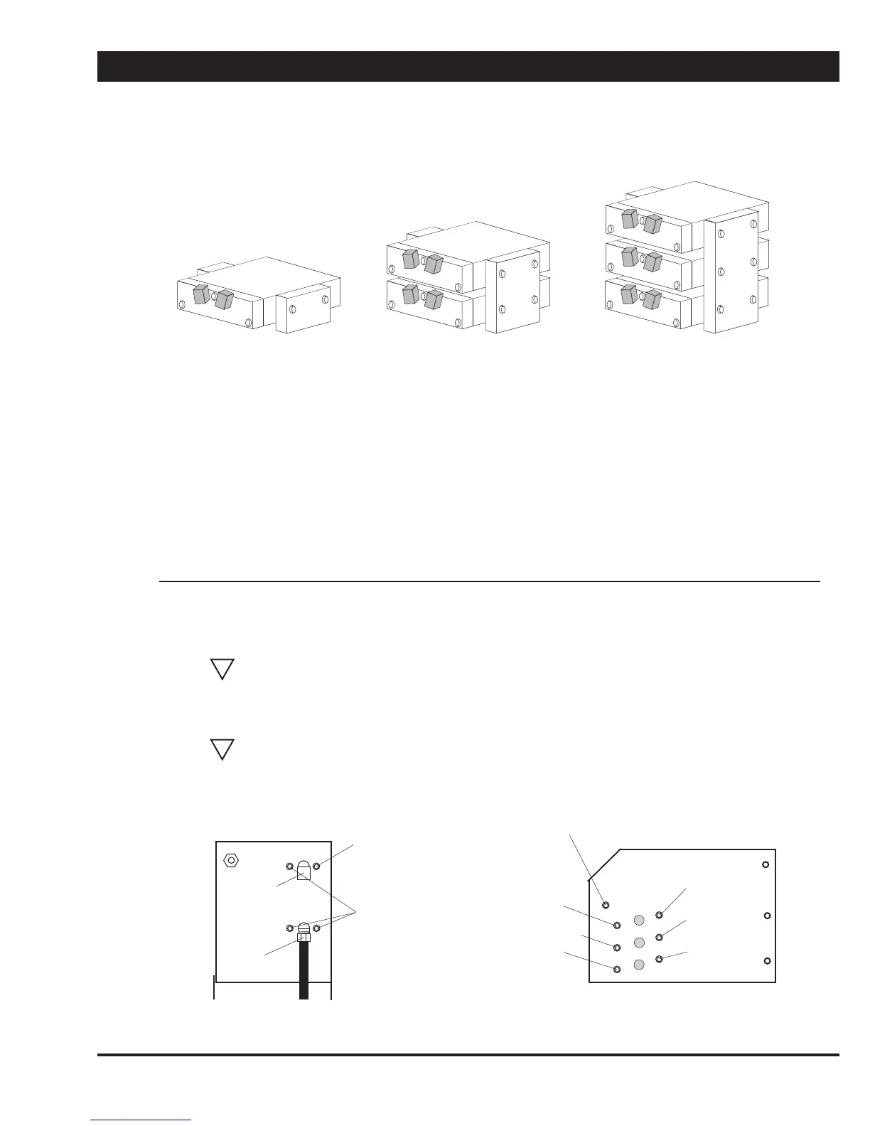
ONE ZONE SYSTEM
(Eg. drive tire
control only)
TWO ZONE SYSTEM
(Eg. drive and steer or drive
and trailer tire control)
THREE ZONE SYSTEM
(Eg. drive, steer and
trailer tire control)
TIREBOSS
TM
Tire Pressure Control systems have either 1, 2 or 3 valve bodies depend-
ing upon the application. The following pages are the rebuild procedures for a single valve
body. Repeat the process for each valve body if required. When working with more than one
valve body ensure all cable harness’s and air lines are returned to the original position when
reassembling the valve bodies. NOTE - One VALVE PACK MAINTENANCE KIT is required
for each valve in the TIREBOSS
TM
system.
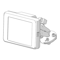
Note.. On three zone systems only, the two front
bolts and lock nuts supporting the Valve Control Module
Bracket will have to be removed in order to tilt bracket to
allow room for valve assembly removal.
VALVE REBUILD PROCEDURE
!
!