5-2
f:tec\manuals\Service\SERVICEv5.indd - V6-0615
Valve Disassembly
CAUTION - Systems with valve heaters only- Do not damage valve heater and foil on bottom
of valve. Do not submerse in cleaning fl uid as this will damage heater.
Remove solenoids from valve and discard O-rings.
See parts BREAKDOWN DRAWING #1.
Remove 3 - 1/4” bolts to disassemble face plate from valve body and discard rubber o-rings
Pull valve cartridges from valve body, using needle nose vice grips on centre allen screw, and put aside for
cleaning at a later stage
Remove 1/4” manifold bolts on side of valve body and discard o-rings
Remove inlet check valve and 1/4” air line fi tting using a 6 point socket only.
CAUTION - Use caution when removing these fi ttings. Do not damage push-to-lock.
Remove paper gaskets from valve body
Clean valve body and manifolds. Blow air through all passages. Ensure all passages are free of debris and
completely free of any cleaning materials before reassembly begins.
Valve Cartridges
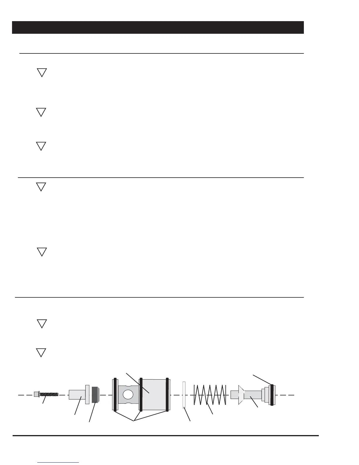
Using two allen wrenches (for old style) or allen wrench and two 1/4”bolts (for new style), disassemble
valve cartridges. Clean all parts. See parts BREAKDOWN DRAWING #3.
NOTE - Do not soak rubber components in varsol or strong cleaners. Rubber will swell and
deteriorate
Assemble valve cartridge with new O-rings (four in total) replacing valve seat poppet. If valve seat or
body is damaged, replace the entire valve cartridge (part #16750).
CAUTION -Take care not to over tighten allen head screw as damage to valve piston
shaft may occur.
VALVE REBUILD PROCEDURE con’t
Disconnection inside box
Remove 1/4” plastic airline from valve
NOTE - It may be necessary to remove line from static tank fi rst to allow enough movement
to disconnect from valve
-Systems with valve heaters only- Cut tie strap from wire bundle and un-plug heater harness
Turn valve body sideways in box to allow access to solenoids. Mark solenoid cables and harness posi-
tions to ensure they are reinstalled in original position during re-assembly.
NOTE - (Red/Green lead on left side and Black/white lead on right side)
Remove solenoid harness’s by removing mount screws.
-Systems with valve heaters only- Remove Robertson #2 screw on thermistor to detach from valve body
Remove valve assembly from box.
NOTE -On three zone systems only, the two front bolts and lock nuts on the Valve Control
Module Bracket will have to be removed in order to allow room to remove valve assembly.
(see page 1)
Replace O-rings
Valve Piston Shaft
Spring
Allen Screw
Brass End Cap
Valve Seat Poppet
Cartridge Body
Spring Washer
Replace O-ring
!
!
!
!
!
!
!