5-3
f:tec\manuals\Service\SERVICEv5.indd - V6-0615
Valve Reassembly
NOTE - Torque all valve body 1/4” bolts to 8 ft/lbs
On assembled valve cartridge, lightly lubricate O-rings, brass bushing at end of cartridges and valve body bore with a light
O-ring lube (LUBRIPLATE No. 105, Motor Assembly Grease). Insert cartridge into bore of valve body. Starting at a slight angle
then aligning straight to insert gently into bore. Ensure free movement, open and close, by manually moving piston end. (Any
interference in movement must be rectifi ed.)
CAUTION - Take extra care not to damage O-rings when installing cartridge.
NOTE - Use anti-seize paste on all bolts and screws in valve assembly. Liquid Pipe thread sealer should be
used in moderation on all pipe fi ttings. (Do not use tefl on tape)
With rebuilt cartridges in place, replace 2 small o-rings and 2 spool valve o-rings. Bolt on face plate with three 1/4” bolts.
Install 2 new solenoid gaskets and reinstall solenoids. NOTE - Do not over tighten solenoid screws. (2.5 in/lbs torque)
Install new inlet check valve (Supplied in maintenance kit). (Ensure no liquid pipe thread sealer is on the inner face).
Reinstall 1/4” airline fi tting into valve body. Install side manifolds with new o-rings. Tighten bolts only fi nger tight at this time.
With side manifolds in position, place assembly upright on work bench. While pushing down on valve body, tighten side
manifold bolts. This will ensure proper alignment of manifolds and valve body.
NOTE - Torque all valve body 1/4” bolts to 8 ft/lbs
Install valve body into box and reinstall thermistor wire (systems with valve heaters only). Plug in solenoid harness on each
solenoid with new square gaskets. Ensure these are installed to original position and valve as marked.
NOTE - Red/Green wire to left side and White/Black wire to right side.
Install and tighten all side 1/4” valve body bolts to box. Now install and tighten bottom 1/4” valve body bolts to box. Install
1/4” air line on valve body
NOTE - Torque all valve body 1/4” bolts to 8 ft/lb
NOTE -On three zone systems only, with a small amount of silicone to seal, reinstall the two front
bolts and lock nuts on the Valve Control Module Bracket as removed on page 5-2)
Box Assembly
Install exhaust and air supply fi ttings on bottom of box. Remove temporary bushing from inside exhaust port.
NOTE - Install exhaust port prior to installing 1/4” bolt on right side of fi tting
-Systems with valve heaters only- Install heater connection harness and tie strap wire bundle together
Air up wet tank to approx 120 psi and ensure that there are no leaks through the valve body assembly
Install 90
o
pipe fi tting on side of box using liquid pipe thread sealer
With metal screen removed from Y-fi lter, check airfl ows by opening and closing each wheel end valve to ensure good airfl ow
from wheels to valve box.
After cleaning metal screen inside Y-fi lter, replace seal washer (Supplied in maintenance kit) and reinstall Y-fi lter plug. See
parts BREAKDOWN DRAWING #4. Reconnect to original position, the Y-fi lter assembly to 90
o
fi tting on side of box
Final Check
Open all wheel valves and ensure that there is no air leaking at the exhaust outlet
With the engine running, turn on the Operator Control Unit. Change setting to highest tire pressure setting and allow tire
pressures to build to this setting.
Leak check all air connections and valve pack assembly using soapy water
Test system functions by changing settings and ensuring system is infl ating and defl ating properly without “WARNINGS”
appearing on Operator Control Unit.
VALVE REBUILD PROCEDURE con’t
Disassembly and Replacement of Orifi ce Filters
Using two wrenches, remove Static Tank Orifi ce located on top of static tank
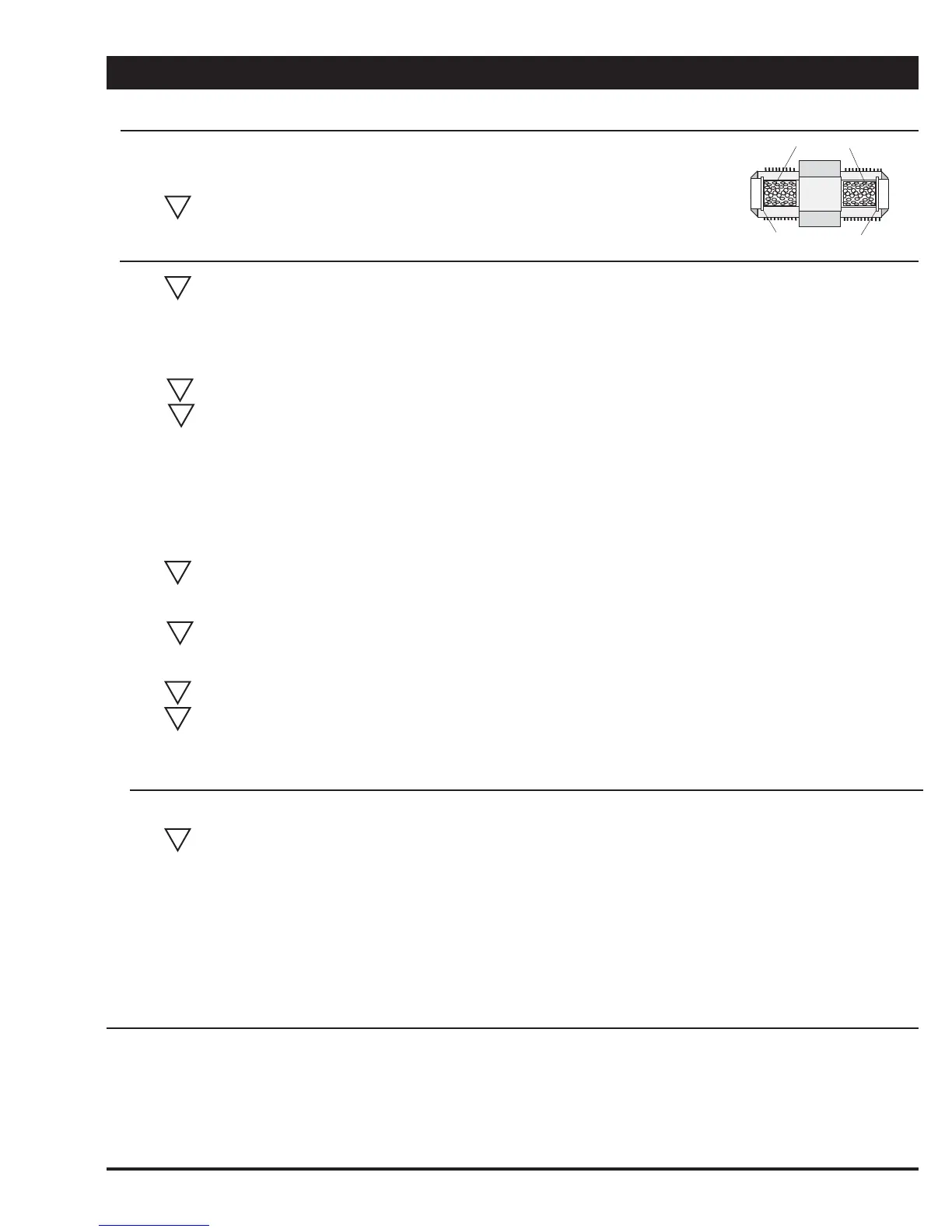
Remove and replace 2 snap rings and fi lters supplied in valve pack maintenance kit.
CAUTION - When re-installing, do not over tighten, as brass fi ttings may split
*Cut-away showing snap rings & fi lters
Filters
Snap Rings
#12
!
!
!
!
!
!
!
!
!


 To Next Page