Trace Engineering DR Series Owner’s Manual - Version 3.2 - 9/7/98 - Page 6
Over Discharge Protection and AC Transfer Voltage
This control enables or disables the over discharge protection system (ODP) and allows adjustment of
the AC transfer voltage. With the dial set to either the left or right side of the scale, transfer voltage can
be adjusted from minimum to maximum. The voltage will vary depending on the model of inverter you
have. See the chart on the next page for transfer voltage values.
ODP (AC Transfer Voltage) Control
Located on the right of the control panel is the OVER-DISCHARGE
PROTECTION control. This circuit is unique to Trace Inverters. Its
purpose is to protect the batteries from being over-discharged. This
circuit monitors both the current being drawn by the inverter and the
battery voltage. Battery voltage alone is not an accurate indicator of
battery condition. The internal resistance of a battery causes its
output voltage to drop when the battery is delivering current. The
smaller the battery, the greater the voltage drop for a given load. This
battery voltage drop due to load is not an indicator of the battery’s
state of charge. The Trace “load compensated” circuit uses
information about the battery bank size, temperature and the load
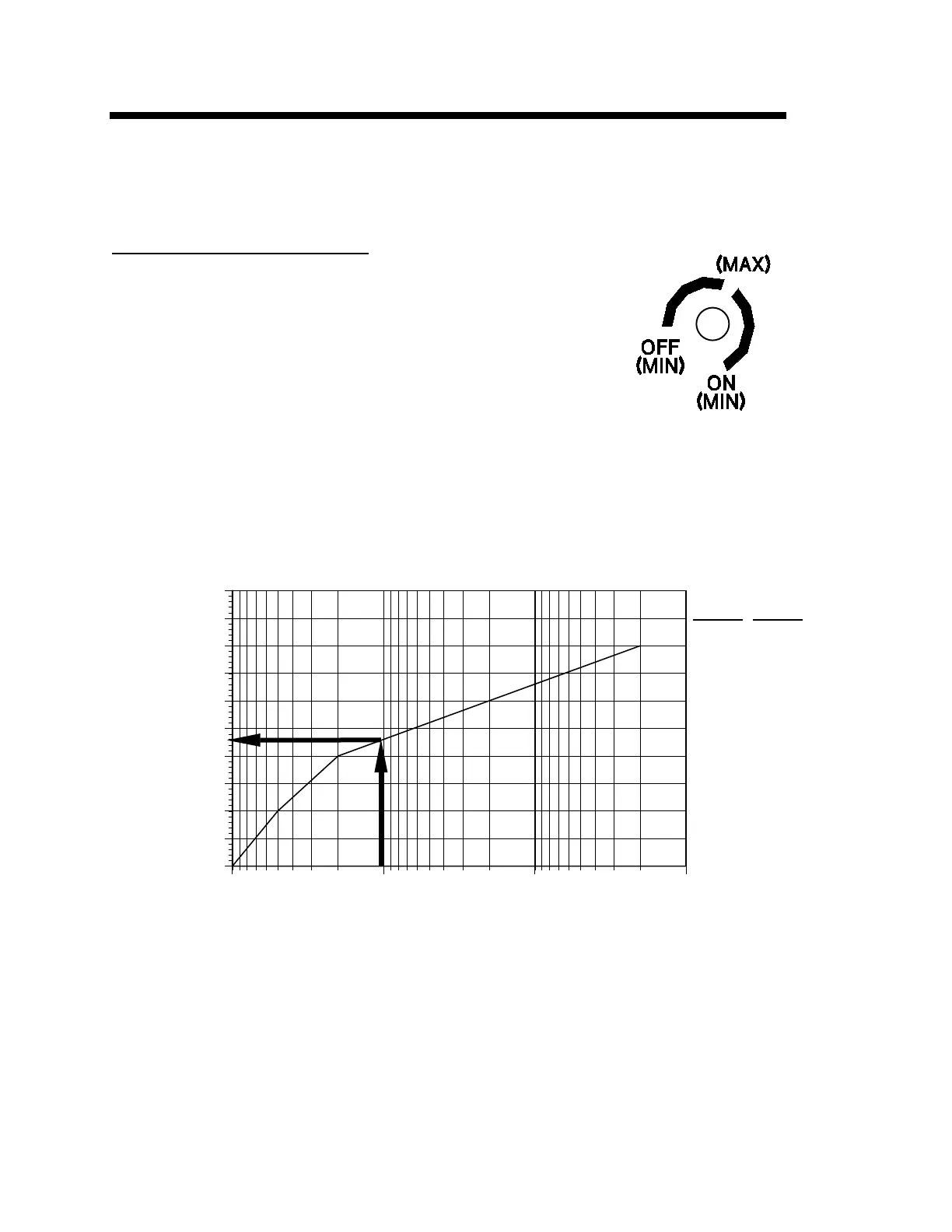
current to derive a corrected battery voltage. Below is a chart showing
the maximum discharge voltage per cell for different load currents and
battery sizes. For example: A battery bank with a 1000 amp-hour capacity being discharged by a load
requiring 100 amps/hour has a factor of 0.1 (100/1000). Enter the chart from the bottom at 0.1,
proceed up to the curve and then to the left. This shows that a minimum voltage of 1.73 volts per cell
should be observed. This chart is useful when customizing the DR inverter to different size systems.
1.5
1.55
1.6
1.65
1.7
1.75
1.8
1.85
1.9
1.95
2
1 0.1 0.01 0.001
Figure 4, Recommended Discharge Cutoff Voltage per Cell
The over discharge protection control is turned clockwise to activate the circuit. It is defeated by
turning the control fully counterclockwise. If the over discharge circuit is defeated, the inverter itself is
protected from low battery voltage conditions by an additional low battery protection circuit which has a
threshold of 8.2 volts DC.
Figure 3, ODP Control
12VDC
24VDC
18.0
19.2
20.4
21.6
22.8
24.0
9.0
9.6
10.2
10.8
11.4
12.0
C
e
l
l
V
o
l
t
a
g
e
Discharge Rate/ Battery Capacity