Trace Engineering DR Series Owner’s Manual - Version 3.2 - 9/7/98 - Page 27
Trace offers a class “T” DC rated fuse block designed specifically for DR series inverter/chargers.
These are available in 110, 200, 300, and 400 Amp sizes. See the Trace price list or contact your
Trace Engineering dealer for more information. (Fuseblocks are Trace part number TFB###. ###
is size in amps of required fuse, i.e. TFB400 is a Trace fuseblock with 400 amp class T fuse.
Replacement fuses are also available.)
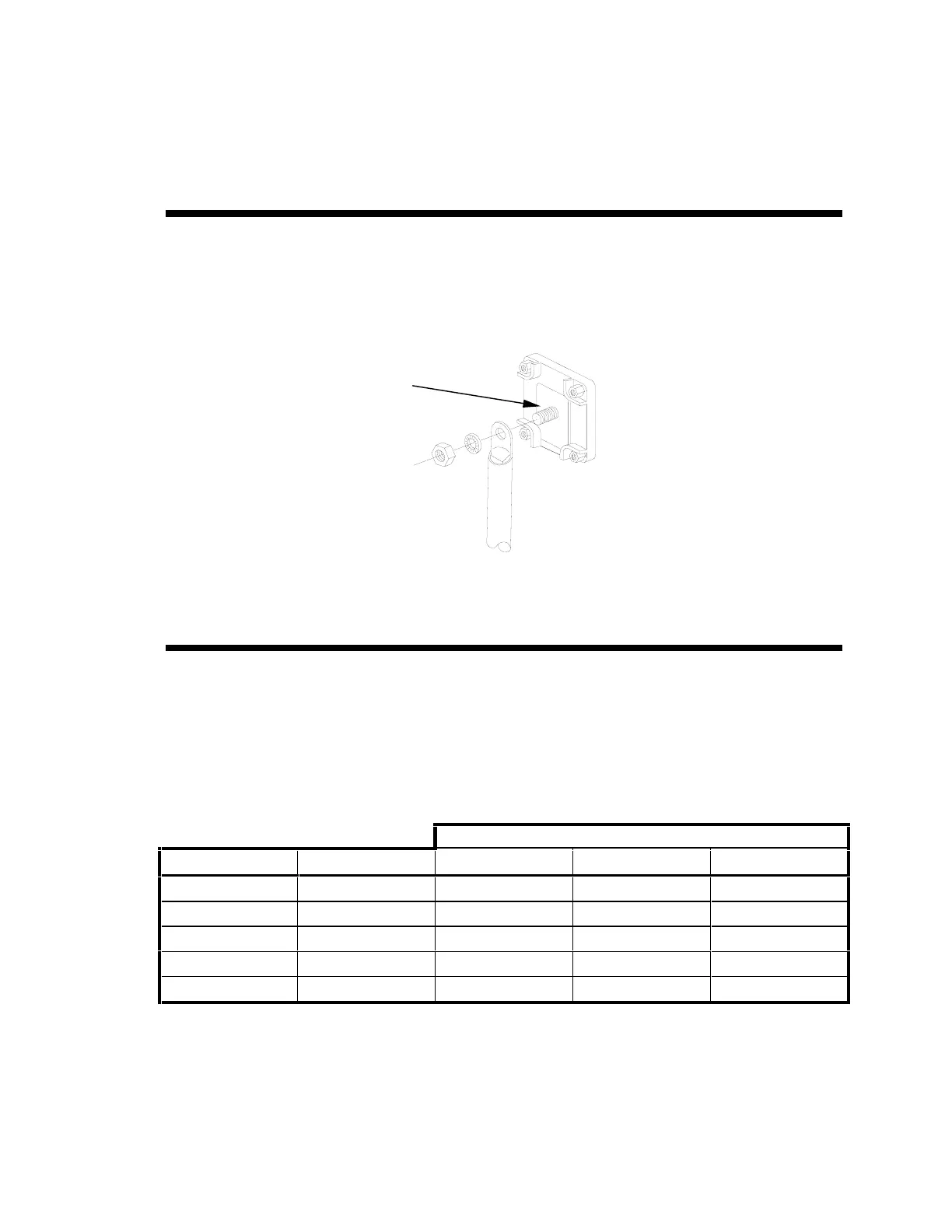
Battery Cable Connection
Observe Battery Polarity! Place the ring terminal over the bolt and directly against the inverter’s
battery terminal. Tighten the 5/16” nut to 10-15 foot/pounds. Do not place anything between the flat
part of the inverter terminal and the battery cable ring terminal or overheating may occur. DO
NOT APPLY ANY TYPE OF ANTI-OXIDANT PASTE TO TERMINALS UNTIL AFTER THE BATTERY
CABLE WIRING IS TORQUED!!
Note: Connecting the battery cables to the inverter DC terminals will cause an arc, usually
accompanied by a “snap”. This is normal don’t let it scare you.
Never disconnect the battery cables while the inverter is delivering power or battery charger is
operating. Always turn the unit off first.
Battery Cable Sizing
The bigger the battery cables the better. Undersized cables result in additional stress on the inverter,
lower efficiency, reduced surge power and lower peak output voltage. Don’t use cables that are too
small in diameter and degrade the efficiency that we have worked so hard to achieve and you have
paid to own. The following table gives recommended minimum cable sizes for various cable run
lengths and inverter voltages.
Table 7, Recommended Battery Cable Size (In Free Air)
Battery cable pair length (one-way)
Model Typical amps Under 3 ft 3 to 5 ft 5 to 10 ft
DR1512 150 amps 00 AWG 00 AWG 0000 AWG
DR2412 240 amps 0000 AWG 0000 AWG not recommended
DR1524 75 amps 00 AWG 00 AWG 0000 AWG
DR2424 120 amps 00 AWG 0000 AWG 0000 AWG
DR3624 180 amps 0000 AWG 0000 AWG 0000 AWG
Note: The term in free air is defined by the NEC as not encased in conduit or raceway.
Caution!! Do NOT place anything
between battery cable ring
terminals and terminals on the
inverter. The terminal stud is not
designed to carry current. Apply
Anti-oxidant paste to terminals
AFTER terminals have been
torqued.
Verify that cable lugs are flush
with the inverter battery
terminals. Tighten battery cables
to terminals, 10-15 foot-pounds.