Trace Engineering DR Series Owner’s Manual - Version 3.2 - 9/7/98 - Page 4
Inverter Operation
Front Panel Controls and LED Indicators
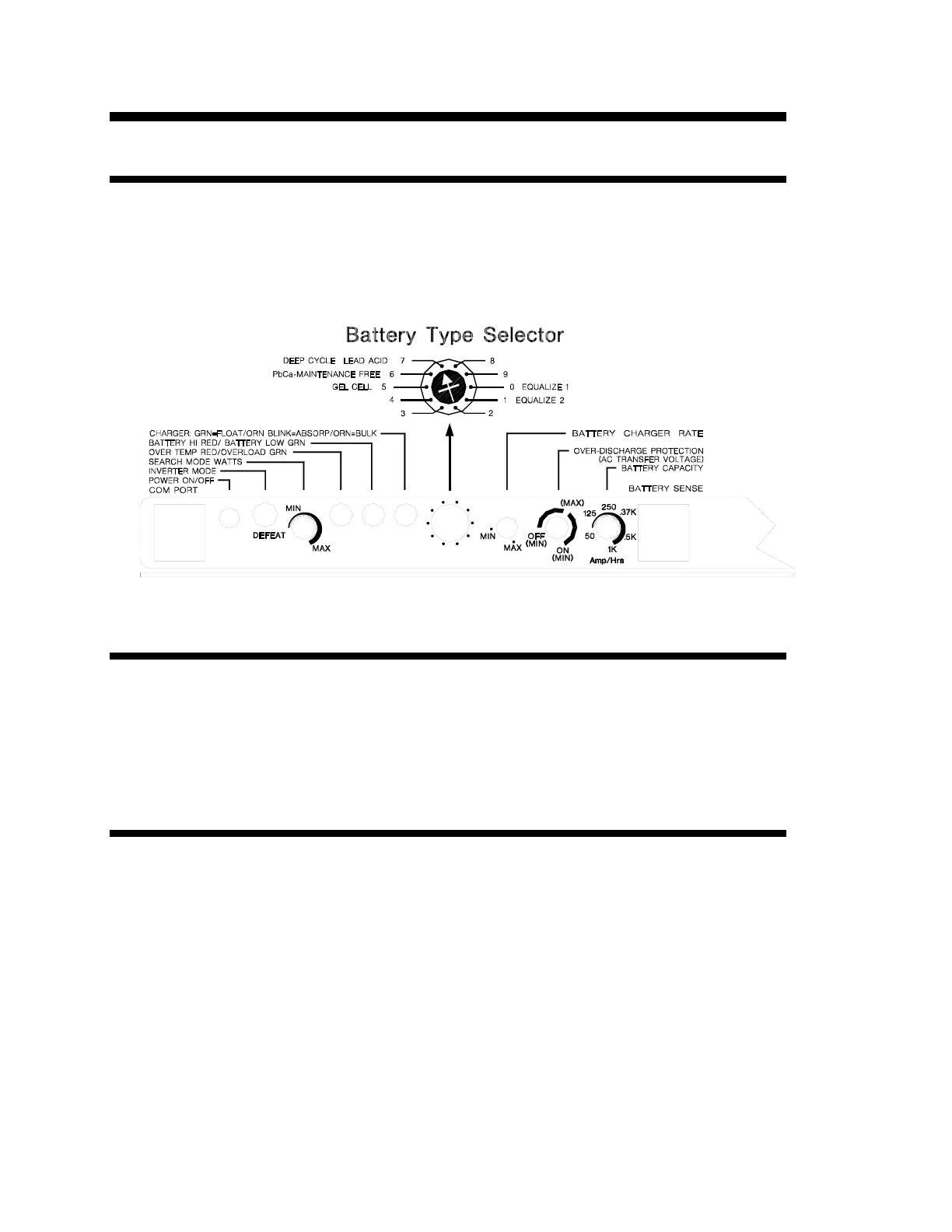
Shown below are the controls and indicator lights on the front of the DR series inverter/charger. These
control and provide information when in either inverter or battery charging mode of operation. All
models of the DR series operate identically.
Figure 2, Control Panel
Power On/Off
Located on the left of the panel is the momentary POWER ON/OFF button. Once the inverter has been
properly installed and the batteries are connected, pressing this button momentarily will alternately turn
the inverter on and off. Each time it is pressed the inverter will sound an audible chirp. Note: When
first connected to batteries, the inverter will run through a self-test, and go to an off state. It may then
be activated by pressing the on/off button. Note: The self-test consists of the control panel lights
lighting up in sequence, the internal cooling fan will run momentarily, and the transfer relay will click
three times.
Inverter Mode LED
This green LED indicator lights when the unit is in the inverter mode (not charging batteries) delivering
full output voltage. When the inverter is in its search mode the green LED will blink about 2-3 times per
second.