Trace Engineering DR Series Owner’s Manual - Version 3.2 - 9/7/98 - Page 29
Stacking Inverters
Note: Stacking allows twice the power output for operating 240VAC loads. “E” and “W” models of
the DR series can not be stacked.
Precautions
•
Only stack like models of the DR inverter. i.e. DR1512 with a DR1512
•
Use only a Trace Engineering stacker cable(DRI). It is not a standard telephone cable.
•
Connect neutrals together close to the inverters
•
Connect the inverters negative terminals together according to this manual.
•
Make and verify all AC and DC connections are made in accordance with NEC code and this
manual. Make sure that all connections are tight. Connect the stacker cable to each inverter’s
COMM port. (Torque battery terminals 10-15 foot-pounds, AC terminals 10-12 inch-pounds)
Connections
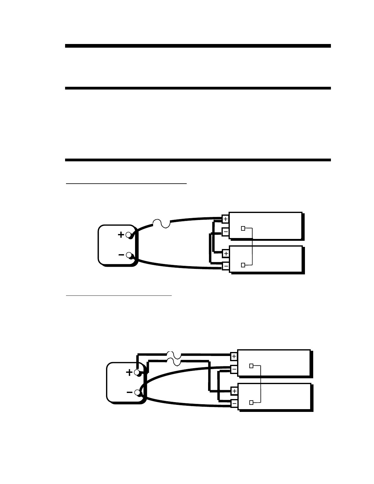
Connection with One DC Disconnect Device
- When stacking two DR units with one DC disconnect
device, connect the units and battery as follows. Connect the negative terminals of the inverters
together, and then attach one of the negatives to the battery. Next connect the positive terminals of the
inverters together, and attach one to the battery. Place the DC disconnect device in the positive line
between the inverter and the battery. (See diagram below)
Stacking DR Inverters with One DC Disconnect or Fuse
Connection with Two DC Disconnects-
If individual disconnects are to be used between the battery
positive and each inverter, connect the stacked system as follows: Connect the negative terminals of
the inverters together and connect each negative terminal to the battery also. Connect each positive
terminal of the inverter to the battery through a DC disconnect in each positive line. Do not tie the
positives together between inverters. (See diagram below)
Once the inverters are connected to the battery, connect the Trace Engineering stacker cable between
the inverters comm ports.
Stacking DR Inverters with Two DC Disconnects or Fuses
BATTERY
DR SERIES INVERTER
DR SERIES INVERTER
DC DISCONNECT
OR FUSE
TRACE STACKER CABLE
(DRI)
BATTERY
DR SERIES INVERTER
DR SERIES INVERTER
TRACE STACKER CABLE
(DRI)
DC DISCONNECTS
OR FUSES