Trace Engineering DR Series Owner’s Manual - Version 3.2 - 9/7/98 - Page 41
Performance Graphs
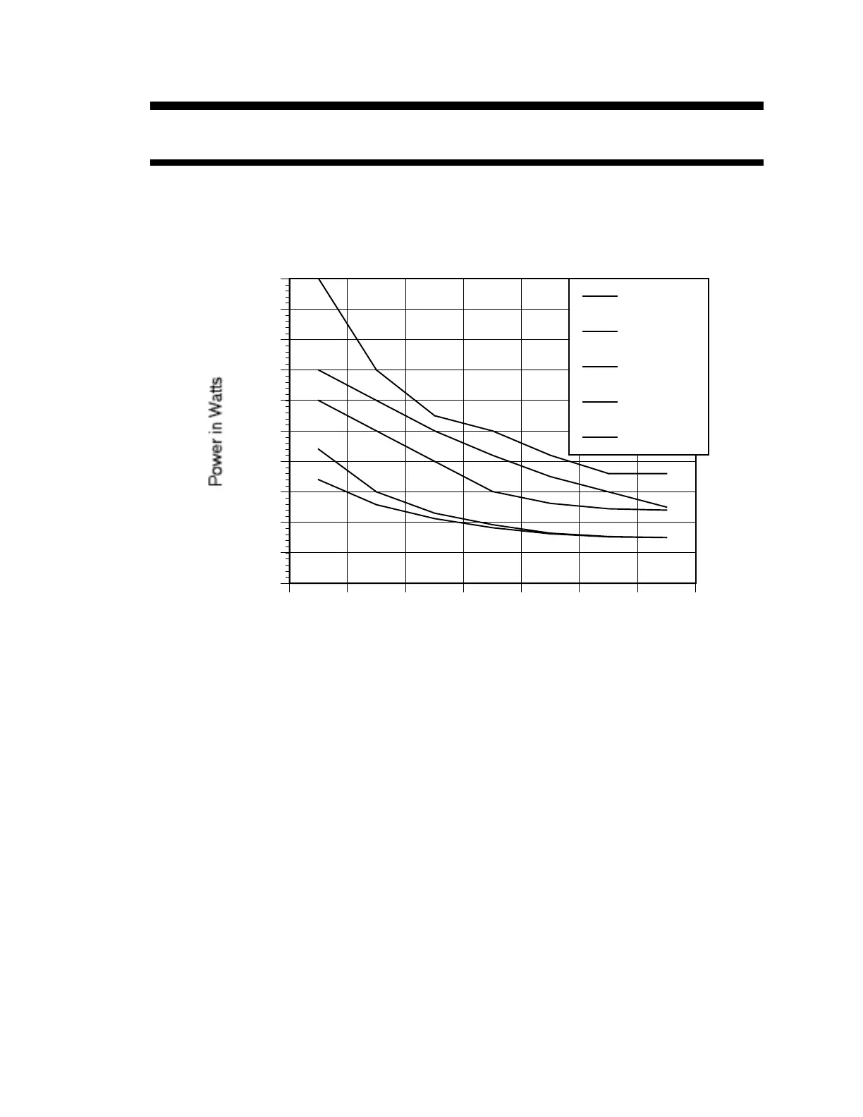
Load Capacity vs. Time
Loads presented to the inverter are seldom constant. Typically, large loads are operated for only short
periods of time. In order to provide the maximum utility, Trace inverters are allowed to operate at
power levels that exceed their continuous power ratings. This graph shows how loads that are larger
than the inverter can sustain continuously can be operated for useful periods of time.
B
B
B
B
B
B
B
J
J
J
J
J
J
J
H
H
H
H
H
H
H
F
F
F
F
F
F
F
G
G
G
G
G
GG
1 2 4 8 15 30 60
0
1000
2000
3000
4000
5000
6000
7000
8000
9000
10000
Time in Minutes
B
DR1524
J
DR1512
H
DR2412
F
DR2424
G
DR3624
Figure 9, Load Capacity vs. Time
The length of time that the inverter can operate at high power is limited by temperature. When large
loads are run, the inverter’s temperature increases. At the point where more heat is created in the
inverter than can be dissipated, its ability to operate becomes time limited. The accompanying graph
represents the relationship between size of load and the time it can be operated.
This graph assumes an ambient operating temperature of 20°C and resistive loads. Reactive loads
(motors, fluorescent lights) and/or elevated ambient temperatures will reduce the time that the inverter
can operate at a particular load level.