Trace Engineering DR Series Owner’s Manual - Version 3.2 - 9/7/98 - Page 7
AC Transfer Voltage
When the AC source (either public power or a generator) fails or falls to a low level (browns out), the
unit changes from battery charger mode to inverter mode. The AC voltage point at which the inverter
decides to change modes is called the AC transfer voltage. It is adjustable from minimum to maximum.
The adjustment is made by rotating the ODP knob between the 9:00 and 1:00 o’clock position if you
want the ODP defeated, or by rotating the knob between 2:00 and 5:00 o’clock if you want the ODP
enabled. As the knob is turned clockwise the transfer voltage increases if the ODP is defeated, or
decreases if the ODP is enabled. It is best to set the transfer voltage by first rotating the control all the
way to the left (off position), then to the desired position. See Figure 3.
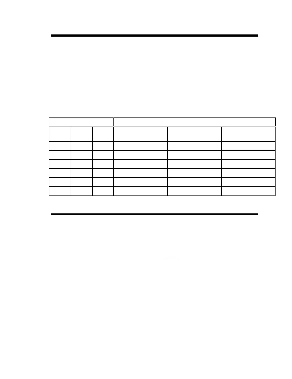
Below is a chart showing the AC transfer voltages depending on the particular AC input/output voltage
of the unit. Note that adjusting the dial to a higher voltage setting results in slightly faster transfer
times, since it will take less of a voltage drop to trigger the transfer. Lower settings are less likely to
cause a transfer due to voltage fluctuations.
ODP ADJUSTMENT AC TRANSFER VOLTAGE
ODP
OFF
ODP
ON
100 - 105 VAC UNITS
(J OR K)
120 VAC UNITS (USA) 220 - 240 VAC UNITS
(W OR E)
9:00 (MIN) 5:00 36 VAC 40 VAC 80 VAC
77 VAC 85 VAC 170 VAC
81 VAC 90 VAC 180 VAC
86 VAC 95 VAC 190 VAC
90 VAC 100 VAC 200 VAC
1:00 (MAX) 2:00 95 VAC 105 VAC 210 VAC
Table 1, AC Transfer Voltage
Battery Bank Capacity
The BATTERY CAPACITY control is used to inform the inverter’s microprocessor about the size of the
battery bank being used. The microprocessor uses the formula of “battery capacity/40” to determine
what current level the bulk/absorption charge terminates (a maximum time of 12 hours is allotted for
bulk/absorption charge) and the float charge stage begins. This allows the inverter to make better
“Over-Discharge Protection” and battery charging decisions. Battery bank size is adjustable from 50 to
1000 (1K) amp-hours. Set this adjustment to the setting closest to the size of your battery bank (in
amp-hours).
Note: .37K = 370 amp-hours, .5K = 500 amp-hours, an 1K = 1000 amp-hours. If your battery bank is
1000 amp-hours or greater, adjust the BATTERY CAPACITY control to the 1K position.