Trace Engineering DR Series Owner’s Manual - Version 3.2 - 9/7/98 - Page 43
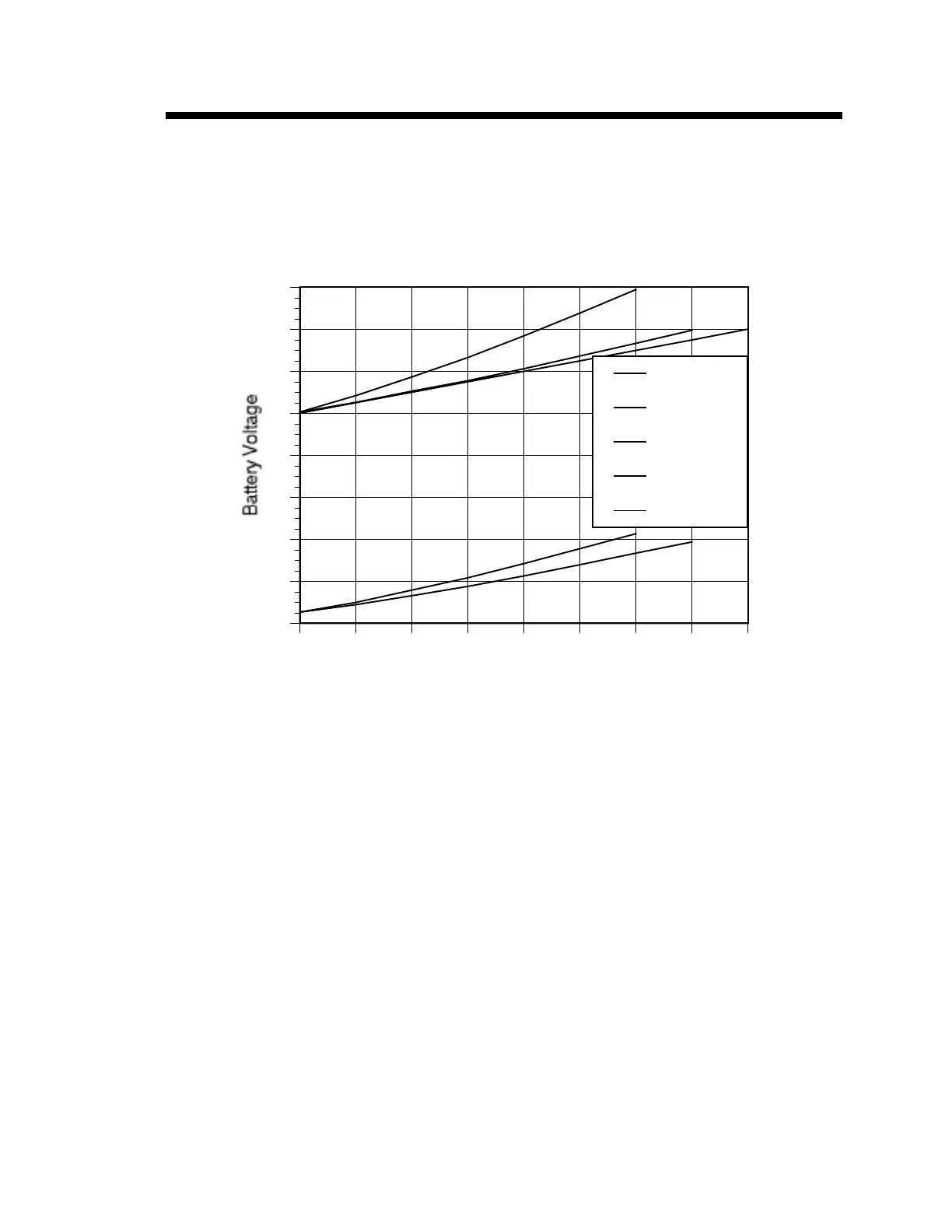
Max Regulated Power vs. Battery Voltage
As the battery voltage is reduced, the maximum regulated power the inverter can produce decreases.
The inverter regulates RMS voltage by changing the width of its output waveform. The graph below
defines the points at which the combination of power and battery voltage results in square wave
output. The area above the line represents combinations of voltage and power at which the inverter’s
output is in regulation. The area below the line shows unregulated operating conditions.
B
B
B
B
B
B
B
J
J
J
J
J
J
J
H
H
H
H
H
H
H
H
F
F
F
F
F
F
F
F
G
G
G
G
G
G
G
G
G
0 500 1000 1500 2000 2500 3000 3500 4000
9
11
13
15
17
19
21
23
25
Power in Watts
B
DR1512
J
DR1524
H
DR2412
F
DR2424
G
DR3624
Figure 11, Maximum Regulated Power Output vs. Battery Voltage