Trace Engineering DR Series Owner’s Manual - Version 3.2 - 9/7/98 - Page 32
Installation Diagrams
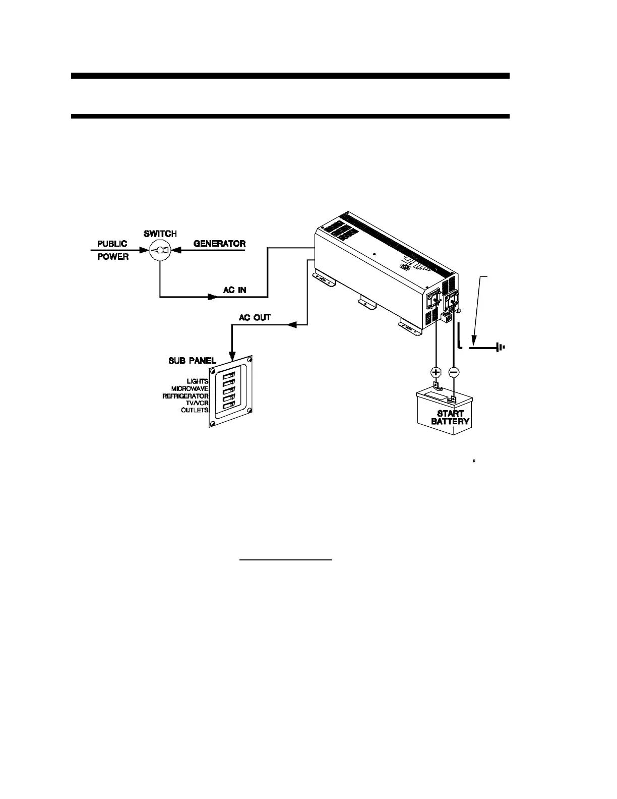
A. Installation with Single AC Panel
In all installations it is important to ensure that AC power from any source (generator, public
power) is never fed to the inverter’s AC output. It is essential that the inverter’s AC output is
not fed to its AC input. The diagram below is simple and meets these requirements. However,
there are two precautions to keep in mind:
Figure 6, Installation with a Single AC Panel
1) With only one AC panel encompassing all loads, the inverter could be connected to loads
which are greater than it can run.
2) The maximum system current is limited by the inverter’s AC input breakers. One breaker
provides 30 amps of pass through current, the other supplies the charger.
The above configuration is acceptable, but not recommended Diagram “B” is preferable because it
isolates the inverter from inappropriate loads.
Safety Ground
- See Table 11
on page 47 for
proper wire
size.