Trace Engineering DR Series Owner’s Manual - Version 3.2 - 9/7/98 - Page 3
Theory of Inverter Operation
Waveform
The output waveform of the inverter is referred to as a modified sine wave. This waveform is suitable
for a wide variety of applications. Induction motors (i.e. refrigerators, drill presses), resistive loads (i.e.
heaters, toasters), universal motors (i.e. hand tools, vacuum cleaners) as well as microwave ovens
and computers are all suitable loads.
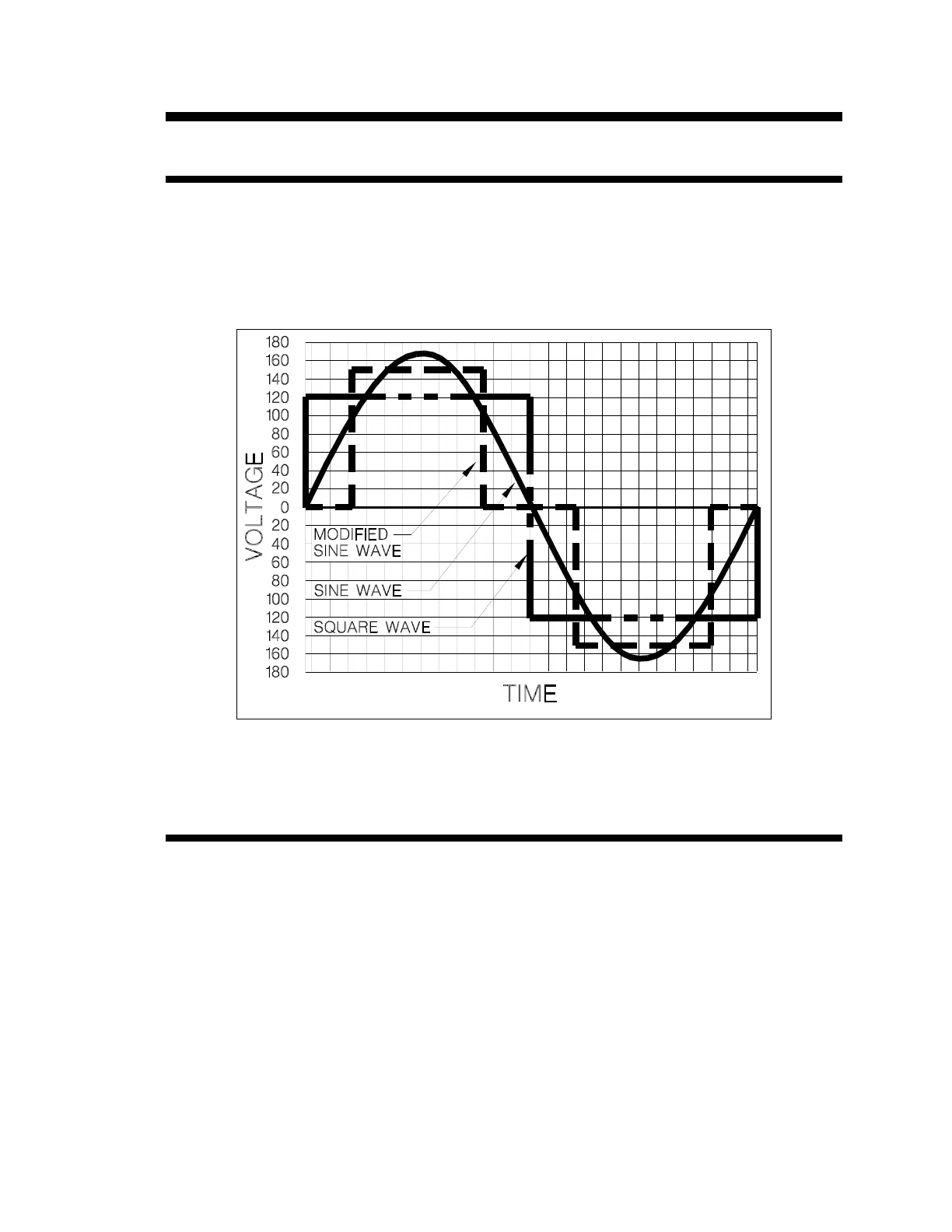
Figure 1 , Comparison of AC Waveforms
The waveform could be more accurately described as a pulse width modified square wave. The
accompanying Figure 1 shows the relationships between square wave, sine wave and modified sine
wave formats.
Regulation
The inverter is RMS voltage regulated. RMS regulation ensures that loads will always have the
same amount of power delivered to them as battery voltage changes. Regulation is achieved by
varying the width of each output pulse in the waveform. Peak voltage is the product of the battery
voltage times the turns ratio of the inverter’s power transformer and is therefore not regulated.