28
TK 55711-19-OP-EN
System Condition Display
Several System Condition LED indicators are located on the left side of the
HMI. These provide additional unit operating information.
SSttaannddbbyy IInnddiiccaattoorr
STBY is illuminated when the system is in Standby or Monitor mode.
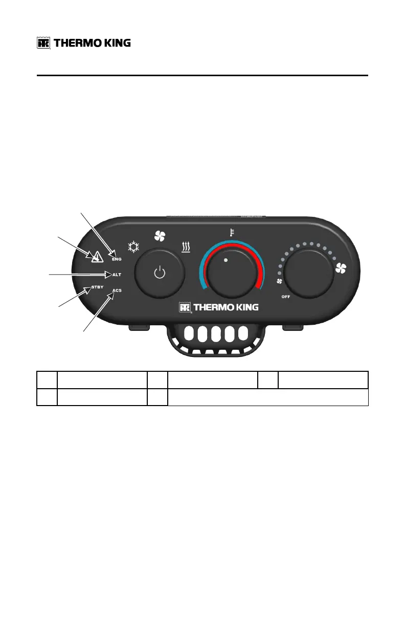
Figure 18. System Condition Display Icons
1.
ENG (engine) Icon
2. ALARM Icon 3.
ALT (alternator) Icon
4. STBY (standby) Icon 5. ACS (air conditioning system) Icon
AAllaarrmm IIccoonn
If the system has an active alarm, the Alarm Icon will illuminate. It will be red
for Shutdown Alarms and yellow for Check Alarms.
AAllaarrmm GGrroouupp IInnddiiccaattoorr
System shutdown alarms have been organized into three general groups to
aid diagnosis. When a Shutdown Alarm is generated, the red Alarm Icon and
the corresponding Alarm Group name will illuminate.
• [[EENNGG]] are APU engine related alarms.
• [[AALLTT]] are alternator or charging system alarms.
• [[AACCSS]] are air conditioning system related alarms.
OOppeerraattiinngg IInnssttrruuccttiioonnss