36
AC-SVX003A-EN
Important:
• See unit nameplate and/or unit submittal
for total shipping weight.
• See following figures for unit lifting
configuration.
• See Dimensions and Weights chapter, or
unit submittal, for lifting point locations.
• Diagram is generic representation of unit.
• The maximum rigging angle at each chiller
lift point is 30° from vertical.
• Do not allow lifting straps to contact unit
during lifting.
To determine the lift configuration, see the following table
and corresponding figures.
Table 16. Lift configuration selections
Condenser
Length
Lift Configuration (Points)
4
Figure 10, p. 36
6
Figure 11, p. 36
8
Figure 12, p. 37
10
Figure 13, p. 37
Used with model number selections:
4V
Digit 42 = X
n/a n/a n/a
5V
Digit 42 = X or T Digit 42 = J Digit 42 = H
n/a
6V n/a
Digit 42 = X or T Digit 42 = J or H
n/a
7V n/a n/a
Digit 40 = X and Digit 42 = X, T or J
Digit 42 = H
Digit 40 = 5, 6, or 7 and Digit 42 = J
8V n/a n/a
Digit 40 = X and Digit 42 = X or T
Digit 42 = J or H
Digit 40 = 5, 6, or 7 and Digit 42 = T
9V n/a n/a n/a All
11V n/a n/a All n/a
Note: Condenser length is designated by model number digit 25. Model number digit 40 designates pump option, and digit 42 is free-cooling.
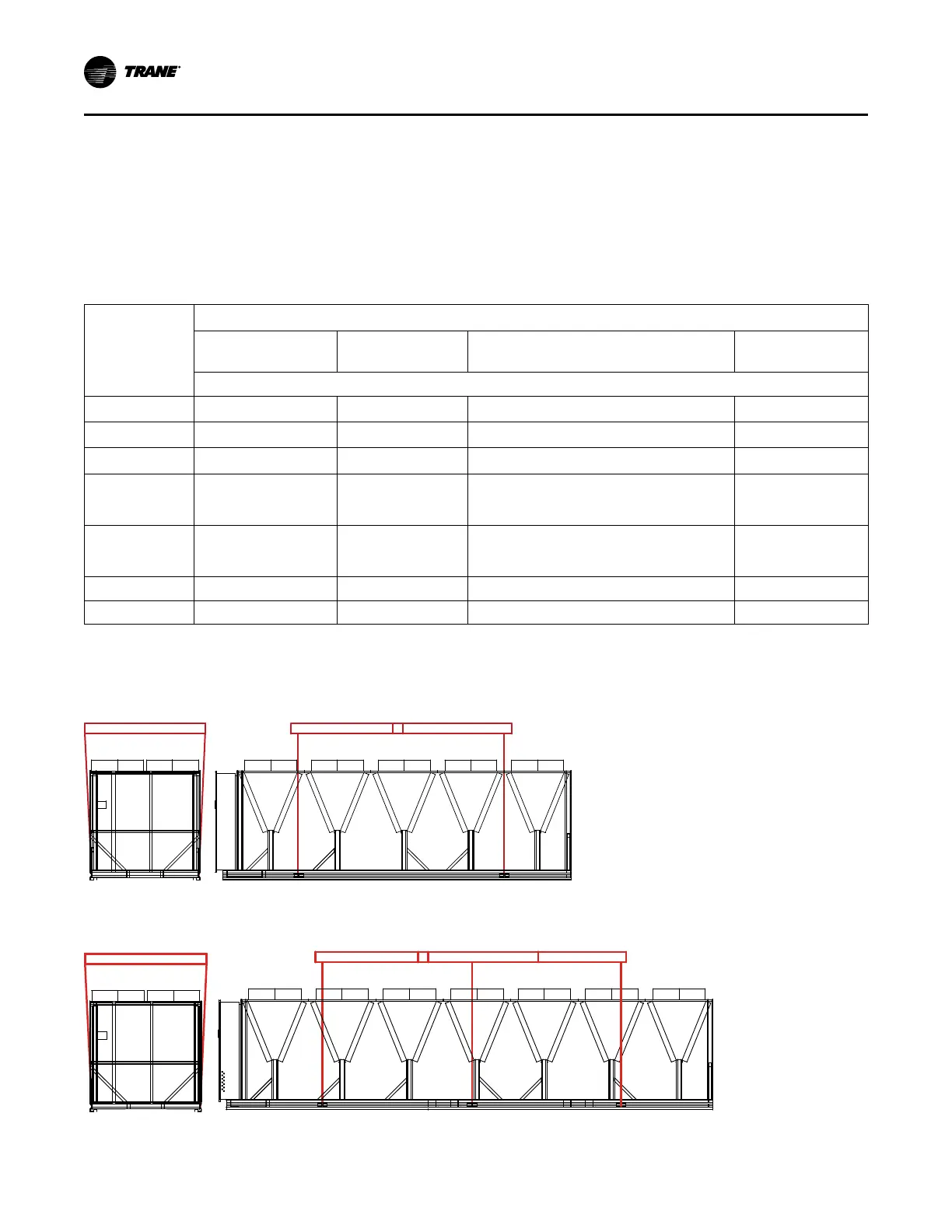
Figure 10. 4–point lift configuration
Spreader bar/lifting rig width: 96 inch
Figure 11. 6–point lift configuration
Spreader bar/lifting rig width: 96 inch
Installation Mechanical

 Loading...

