24 SO-SVN038A-EN
Programming
Programming the Symbio 800 AdaptiView
Note: For more information regarding the use of the Tracer
TU service tool, installation, operation and
programming of the Symbio™ 800 controller,
operation of the control system, and a guide to the
diagnostics and troubleshooting of the control system,
refer to the following manuals (or their most recent
versions):
• TU Service Tool - User Guide (BAS-SVU047*-EN)
• Tracer® TU Service Tool For Water-Cooled CenTraVac™
Chillers with Symbio™ Controls - Programming Guide
(CTV-SVP004*-EN)
• CenTraVac™ Water-cooled Chillers Models CVHE, CVHF,
and CVHG With Symbio™ Controls - Installation,
Operation, and Maintenance (CVHE-SVX005*-EN)
• Tracer Symbio Panel Upgrade - Programming Guide
(CVRF-SVP01*-EN)
• CenTraVac™ Water-Cooled Chillers AdaptiView™
Display with Symbio™ Controls - User Guide
(CTV-SVU004*-EN)
• CenTraVac™ Water-cooled Chillers with Symbio™
Controls Diagnostic Descriptions, Troubleshooting Tables,
and Control Component Overview - Diagnostics Manual
(CTV-SVD005*-EN)
1. Power the technician laptop using a working AC power
adapter.
2. Connect the computer with the Tracer® TU service tool
software to the service port of the Symbio™ 800 controller
with a USB type A/B cable.
3. Open Tracer TU.
4. Upgrade controller firmware as follows:
a. In the Utilities menu, select File Transfer Utility.
b. In the File Transfer dialog box, select Symbio 800
controller, and click Next.
c. Browse to the firmware file and click Next.
d. Click Start.
e. When upgrade is complete, click Finish.
NOTICE
Separate AC Power Required for
Computers when Working on Symbio
800!
When doing any service work on a Tracer AdaptiView
control system that requires connecting a laptop
computer running Tracer TU service tool software to
the Symbio 800 controller, the laptop must be operated
from a SEPARATE AC power source AT ALL TIMES.
NEVER run the laptop on internal battery power alone
while connected to a Symbio 800 controller! Should the
computer’s internal battery die or malfunction while
connected to a Symbio 800, fatal corruptions could
occur to the electronic files within the controller that
will render it completely inoperable and unable to
accept new programming, requiring it to be replaced
with new Symbio 800. Damaging a Symbio 800
controller in this manner is not covered under any
warranty!
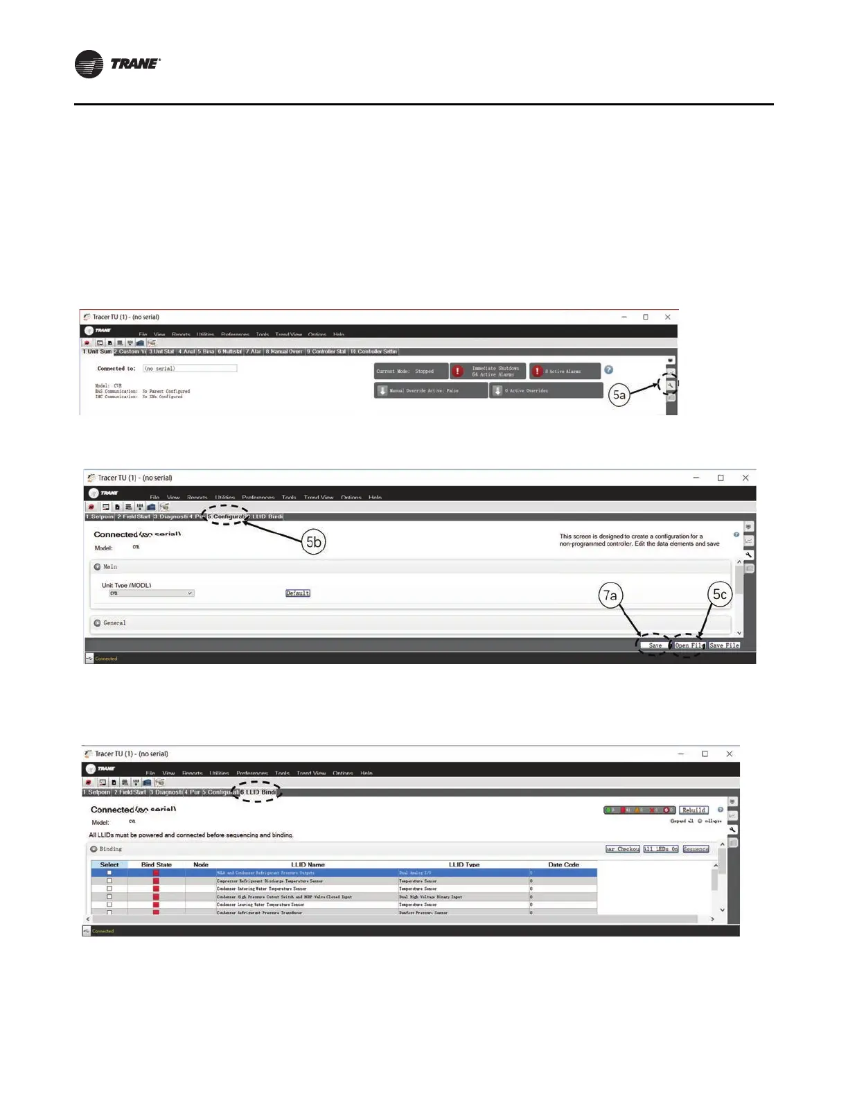
Figure 41. Application software download