Installation
WSHP-SVX01L-EN 59
Low-voltage connection diagrams for basic and deluxe 24
V control packages mounted on ½-5 ton equipment sizes
are shown in Figure 58, p. 59.
Low-voltage connection diagrams for deluxe 24V control
packages for these thermostats mounted on 6-25 ton
equipment sizes are shown in Figure 59, p. 59.
For controls using DC analog input/outputs, see
appropriate installation, operation and diagnostic
manuals for connection. WSHP-IOP-2 (ZN510) and WSHP-
PRB002-EN (ZN524).
Blower Motor Speed-Tap Retrofit
Note: For GEH/V ½-5 ton units only.
Motors installed in the unit include 4-speed and 3-speed
configurations. All voltages include a 4-speed
configuration, with the exception of 380V, 415V, 460V
which contain a 3-speed arrangement and 575V which
contains a 2-speed arrangement. To modify the rpm of the
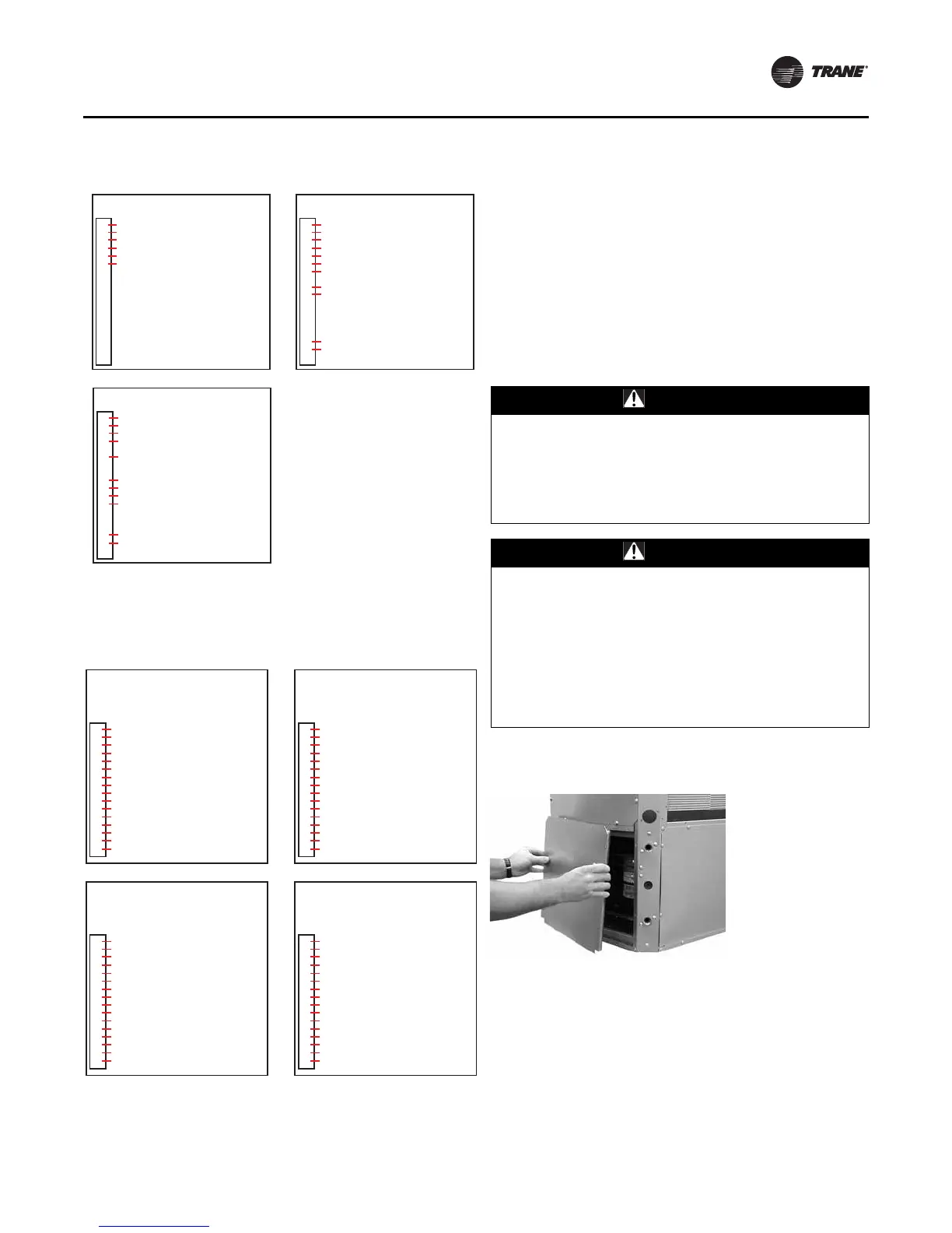
motor, the following steps must be followed.
1. Remove service access panel at the unit front.
Figure 58. Low-voltage connection (GEH/V ½-5 ton and
EXH/V 1½-6 ton equipment)
Figure 59. Low-voltage connection (GEH/V 6-25 ton)
Basic Controls Wall Mounted Thermostat
1
2
3
4
5
6
7
8
9
10
11
12
13
14
15
16
17
18
1TB1
24 VAC
FAN
REVERSING VALVE (COOL)
COMPRESSOR & VAR SPD PUMP SOLENOID
24 VAC GENERAL ALARM OUTPUT
24 VAC COMMON & VAR SPD PUMP SOLENOID
Deluxe Controls Wall Mounted Thermostat
1
2
3
4
5
6
7
8
9
10
11
12
13
14
15
16
17
18
1TB1
24 VAC
FAN
REVERSING VALVE (COOL)
COMPRESSOR & VAR SPD PUMP SOLENOID
24 VAC COMMON & VAR SPD PUMP SOLENOID
ELECTRIC HEAT (COOL ONLY W/ ELEC HT UNIT)
24 VAC COMPRESSOR DISABLE INPUT
24 VAC COMPRESSOR DISABLE INPUT
ALARM CONTACT OUTPUT
ALARM CONTACT OUTPUT
Deluxe Controls With Reheat
1
2
3
4
5
6
7
8
9
10
11
12
13
14
15
16
17
18
1TB1
24 VAC
FAN
REVERSING VALVE (COOL)
COMPRESSOR
24 VAC COMMON & VAR SPD PUMP SOLENOID
24 VAC COMPRESSOR DISABLE INPUT
24 VAC COMPRESSOR DISABLE INPUT
HUMIDISTAT
VAR SPD PUMP SOLENOID
ALARM CONTACT OUTPUT
ALARM CONTACT OUTPUT
Deluxe Controls with
-all Heat Pump Units w/ Reheat
using X13511090010 (T8511)
1
2
3
4
5
6
7
8
9
10
11
12
13
14
15
16
1TB2
24 VAC (R)
FAN (G)
COMPRESSOR 1 (Y1)
COMPRESSOR 2 (Y2)
REVERSING VALVE (0) & HUMIDISTAT
24 VAC COMMON (C) & WATER ISOLATION VA
COMPRESSOR DISABLE
COMPRESSOR DISABLE
ALARM
ALARM
ELECTRIC HEAT
ELECTRIC HEAT
HUMIDISTAT
WATER ISOLATION VALVE
3RD STAGE HEAT (W3)
NOT USED
Deluxe Controls with
-all Heat Pump Units w/ Reheat
using X13511091010/X13511092010 (T7300)
1
2
3
4
5
6
7
8
9
10
11
12
13
14
15
16
1TB2
24 VAC (R)
FAN (G)
COMPRESSOR 1 (Y1)
COMPRESSOR 2 (Y2)
REVERSING VALVE (0) & HUMIDISTAT
24 VAC COMMON (X) & WATER ISOLATION VA
COMPRESSOR DISABLE
COMPRESSOR DISABLE
ALARM
ALARM
ELECTRIC HEAT
ELECTRIC HEAT
HUMIDISTAT
WATER ISOLATION VALVE
3RD STAGE HEAT (W1)
NOT USED
Deluxe Controls with
-all Heat Pump Units without Reheat
using X13511090010 (T8511)
1
2
3
4
5
6
7
8
9
10
11
12
13
14
15
16
1TB2
24 VAC (R)
FAN (G)
COMPRESSOR 1 (Y1) & WATER ISOLATION VA
COMPRESSOR 2 (Y2)
REVERSING VALVE (0) & HUMIDISTAT
24 VAC COMMON (C) & WATER ISOLATION VA
COMPRESSOR DISABLE
COMPRESSOR DISABLE
ALARM
ALARM
ELECTRIC HEAT
ELECTRIC HEAT
HUMIDISTAT
NOT USED
3RD STAGE HEAT (W3)
NOT USED
Deluxe Controls with
-all Heat Pump Units without Reheat
using X13511091010/X13511092010 (T7300)
1
2
3
4
5
6
7
8
9
10
11
12
13
14
15
16
1TB2
24 VAC (R)
FAN (G)
COMPRESSOR 1 (Y1) & WATER ISOLATION VA
COMPRESSOR 2 (Y2)
REVERSING VALVE (0) & HUMIDISTAT
24 VAC COMMON (X) & WATER ISOLATION VA
COMPRESSOR DISABLE
COMPRESSOR DISABLE
ALARM
ALARM
ELECTRIC HEAT
ELECTRIC HEAT
HUMIDISTAT
NOT USED
3RD STAGE HEAT (W1)
NOT USED
WARNING
Hazardous Voltage!
Disconnect all electric power, including remote
disconnects before servicing. Follow proper lockout/
tagout procedures to ensure the power can not be
inadvertently energized. Failure to disconnect power
before servicing could result in death or serious injury.
WARNING
Proper Field Wiring and Grounding
Required!
All field wiring MUST be performed by qualified
personnel. Improperly installed and grounded field
wiring poses FIRE and ELECTROCUTION hazards. To
avoid these hazards, you MUST follow requirements for
field wiring installation and grounding as described in
NEC and your local/state electrical codes. Failure to
follow codes could result in death or serious injury.
Figure 60. Service access panel