Unit Start Up
130 RT-SVX36K-EN
Evaporative Condenser Startup
Important: Water treatment by a qualified water
treatment expert is required to ensure
proper equipment life and product
performance. Dolphin Water Care is an
option offered byTrane that is NOT a
substitute for regular water treatment by a
qualified water treatment professional. If a
water treatment system is not operating on
the unit, do not proceed.
Startup for evaporative and air-cooled condensers is
initially the same. In addition, the following is required for
evaporative condensers prior to startup:
• All water and drain connections must be checked and
verified
• Evaporative condensers will ship with a fan support
bracket to reduce damage caused by vibration during
shipment.The shipping support brackets must be
removed prior to unit startup. See “To remove
shipping brackets,” p. 130 and Figure 85, p. 131 for
removal instructions.
• Verify that inlet water pressure is 35-60 PSIG, dynamic
pressure (measured with the valve open)
• Verify that drain valve is set to “drain during power
loss” or “hold during power loss” per job specification
• Upon a call for cooling, the sump will fill with water.
Verify that the sump fills to a level within the slot on the
max float bracket as shown in Figure 86, p. 131.
To remove shipping brackets
Important: Remove fan shipping brackets before
startup. Failure to remove brackets could
result in fan damage.
Evaporative condensers are shipped with fan shipping
brackets to reduce damage caused by vibration during
shipment.The fan shipping brackets must be removed
prior to unit startup.
To remove the shipping brackets start from the side
opposite to the drain actuator:
1. Loosen the screw for the bracket that holds the inlet
louvers below the door side.
2. Remove inlet louvers and set to the side.
Note: Service technician may need to step on the
horizontal surface of FRP coated base.
Step with care.
3. Unscrew the bolt in the middle of the door. Keep the
bolt in a safe place.
4. Lift one door with handle until it touches the top.
Swivel bottom of door to remove it from the door
opening and set it to the side.
5. Slide and remove the middle mist eliminator section
so that the shipping bracket is visible.
6. Use screw gun to unscrew the two screws that hold the
fan shipping bracket.The bracket should drop down
but still remain engaged with a hook on the bracket.
7. Go to the other side of the unit and follow the
procedure for inlet louver and door removal
(see steps1-6).
8. Hold the bracket with one hand and remove remaining
two screws.
9. Remove the bracket and all the removed screws from
the unit.
Important: Make sure there are no screws remaining in
the coil area.
10. Reinstall inlet louvers, mist eliminators and louvers.
11. Check that the direction of arrow on the inlet louver is
correct.
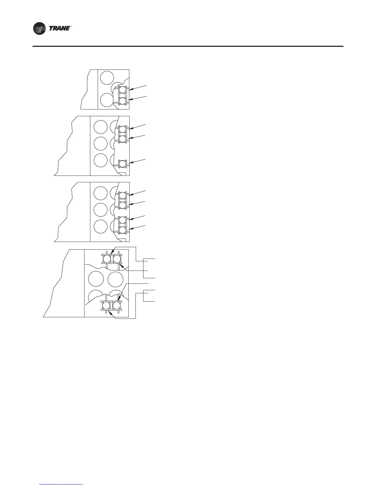
Figure 84. Compressor locations
20-36 Ton
40-89 Ton
Compressor A
HI Designator “K10”
Compressor B
HI Designator “K11”
Compressor 2B
HI Designator “K4”
Compressor 2A
HI Designator “K3”
Compressor 1A
HI Designator “K11”
Compressor 1B
HI Designator “K12”
40-70T
variable speed
compressor
Compressor 2B
HI Designator “K4”
Compressor 2A
HI Designator “K3”
Compressor 1A
HI Designator “K11”
Compressor 1B
HI Designator “K12”
Compressor 2B
HI Designator “K4”
Compressor 2A
HI Designator “K3”
Compressor 1A
HI Designator “K11”
90-130 Ton

 Loading...


