Unit Start Up
RT-SVX36K-EN 127
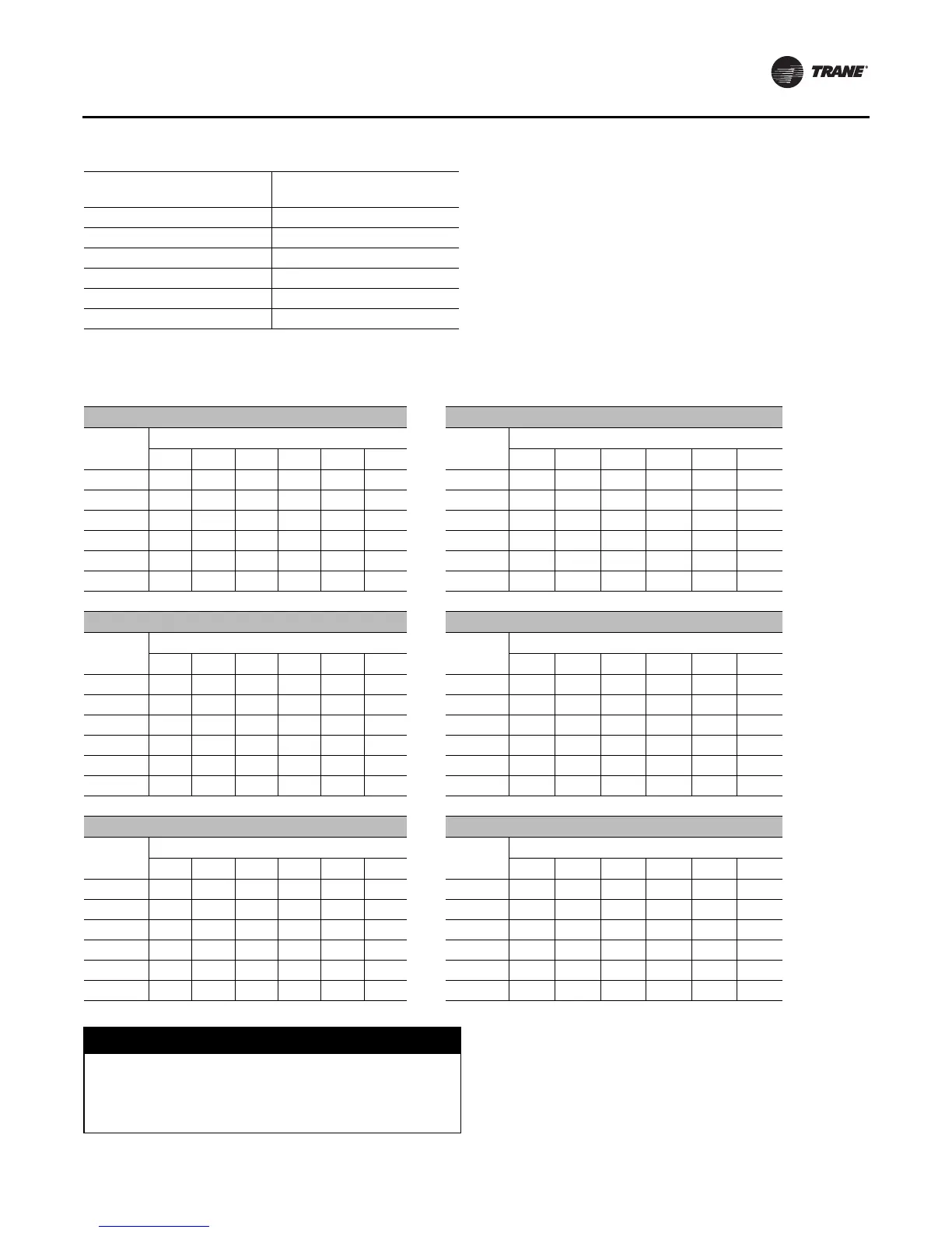
Use Table 58, p. 127 to select the appropriate crank arm
hole configuration based on the;
a. specific unit
b. operating CFM
c. and return static pressure.
Compressor Start-Up (All Systems)
1. Ensure that the “System” selection switch at the
remote panel is in the “Off” position.
2. Before closing the disconnect switch, ensure that the
compressor discharge service valve and the liquid line
service valve for each circuit is back seated.
Table 57. F/A Damper travel adjustment
Position of Connecting Rod
(Figure 81, p. 117)
Damper Crank Arm Hole
Configuration
Position #1 2 - 3
Position #2 2 - 4
Position #3 2 - 5
Position #4 2 - 6
Position #5 1 - 8
Position #6 1 - 7
Note: As shipped from the factory, the connect rod is installed in Position
#1.
Table 58. Outside air damper pressure drop (inches w.c.) — Air-Cooled and Evaporative Condensing
(20, 25 Ton and 24, 29 Ton) Units (50, 55 and 59 Ton) Units
CFM
Damper Position
CFM
Damper Position
#1 #2 #3 #4 #5 #6 #1 #2 #3 #4 #5 #6
4000 0.03 0.04 0.06 0.13 0.16 0.33 10000 0.03 0.04 0.09 0.18 0.23 0.55
6000 0.03 0.04 0.10 0.20 0.30 0.90 14000 0.09 0.12 0.20 0.35 0.50 1.36
8000 0.19 0.21 0.32 0.52 0.75 1.75 18000 0.31 0.36 0.50 0.79 1.10 -
9000 0.30 0.35 0.48 0.76 1.08 2.40 20000 0.45 0.51 0.70 1.05 1.57 -
10000 0.45 0.51 0.70 1.05 1.57 - 22000 0.58 0.66 0.75 1.30 1.95 -
11000 0.62 0.71 0.95 1.42 2.15 - 24000 0.75 0.88 1.10 1.75 2.50 -
(30, 36 Ton) Units (60, 70, 75 Ton and 73, 80, 89 Ton) Units
CFM
Damper Position
CFM
Damper Position
#1 #2 #3 #4 #5 #6 #1 #2 #3 #4 #5 #6
6000 0.03 0.04 0.07 0.15 0.20 0.43 14000 0.03 0.04 0.12 0.25 0.35 1.05
8000 0.03 0.05 0.11 0.21 0.30 0.90 18000 0.19 0.21 0.32 0.52 0.75 1.75
10000 0.15 0.19 0.26 0.43 0.62 1.50 22000 0.45 0.51 0.70 1.05 1.57 -
11000 0.20 0.25 0.37 0.60 0.85 1.85 26000 0.70 0.80 1.02 1.58 2.30 -
12000 0.31 0.36 0.50 0.79 1.10 2.40 28000 0.88 1.03 1.30 2.20 - -
13000 0.42 0.48 0.62 0.97 1.42 - 30000 1.05 1.22 1.55 2.65 - -
(40, 48 Ton) Units (90 - 130 Ton) Units
CFM
Damper Position
CFM
Damper Position
#1 #2 #3 #4 #5 #6 #1 #2 #3 #4 #5 #6
8000 0.03 0.04 0.08 0.16 0.21 0.52 27000 0.31 0.36 0.50 0.79 1.10 2.40
10000 0.03 0.05 0.11 0.21 0.30 0.90 32000 0.55 0.64 0.72 1.25 1.88 -
12000 0.10 0.13 0.21 0.38 0.55 1.40 36000 0.75 0.88 1.10 1.75 2.50 -
14000 0.20 0.25 0.37 0.60 0.85 1.85 40000 1.00 1.18 1.50 2.50 - -
16000 0.41 0.46 0.60 0.94 1.38 - 43000 1.20 1.42 1.92 - - -
18000 0.56 0.65 0.74 1.28 1.92 - 46000 1.40 1.58 2.29 - - -
NOTICE:
Compressors Failure!
Unit must be powered and crankcase heaters energized
at least 8 hours BEFORE compressors are started. This
will protect the compressors from premature failure.

 Loading...


