Unit Start Up
154 RT-SVX36K-EN
Final Unit Checkout
After completing all of the checkout and start-up
procedures outlined in the previous sections (i.e.,
operating the unit in each of its Modes through all
available stages of cooling and heating), perform these
final checks before leaving the unit:
1. Close the disconnect switch or circuit protector switch
that provides the supply power to the unit's terminal
block 1TB1 or the unit mounted disconnect switch
1S14.
HIGH VOLTAGE IS PRESENT ATTERMINAL BLOCK 1TB1
OR UNIT DISCONNECT SWITCH 1S14.
2. Turn the 115 volt control circuit switch 1S1 “Off”.
3. Turn the 24 volt control circuit switch 1S70 to the “On”
position.
4. At the Human Interface Module, press the “SETUP”
key.The LCD screen will display various preset
“parameters of operation” based on the unit type, size,
and the installed options. Compare the factory preset
information to the specified application requirements.
If adjustments are required, follow the step-by-step
instructions provided in the appropriate programming
manual for CV or VAV applications.
5. Program the Night Setback (NSB) panel (if applicable)
for proper unoccupied operation. Refer to the
programming instructions for the specific panel.
6. Verify that the Remote panel “System” selection
switch, “Fan” selection switch, and “Zone
Temperature” settings for constant volume systems
are correct.
7. Verify that the Remote panel “System” selection
switch and the “Supply AirTemperature” settings for
DischargeTemperature Control systems are correct.
8. Inspect the unit for misplaced tools, hardware, and
debris.
9. Turn the 115 volt control circuit switch 1S1 “On”.
10. Press the “AUTO” key at the Human Interface Module
to begin system operation.The system will start
automatically once the dampers modulate and a
request for either heating or cooling has been given.
11. Verify that all exterior panels including the control
panel doors and condenser grilles are secured in place.
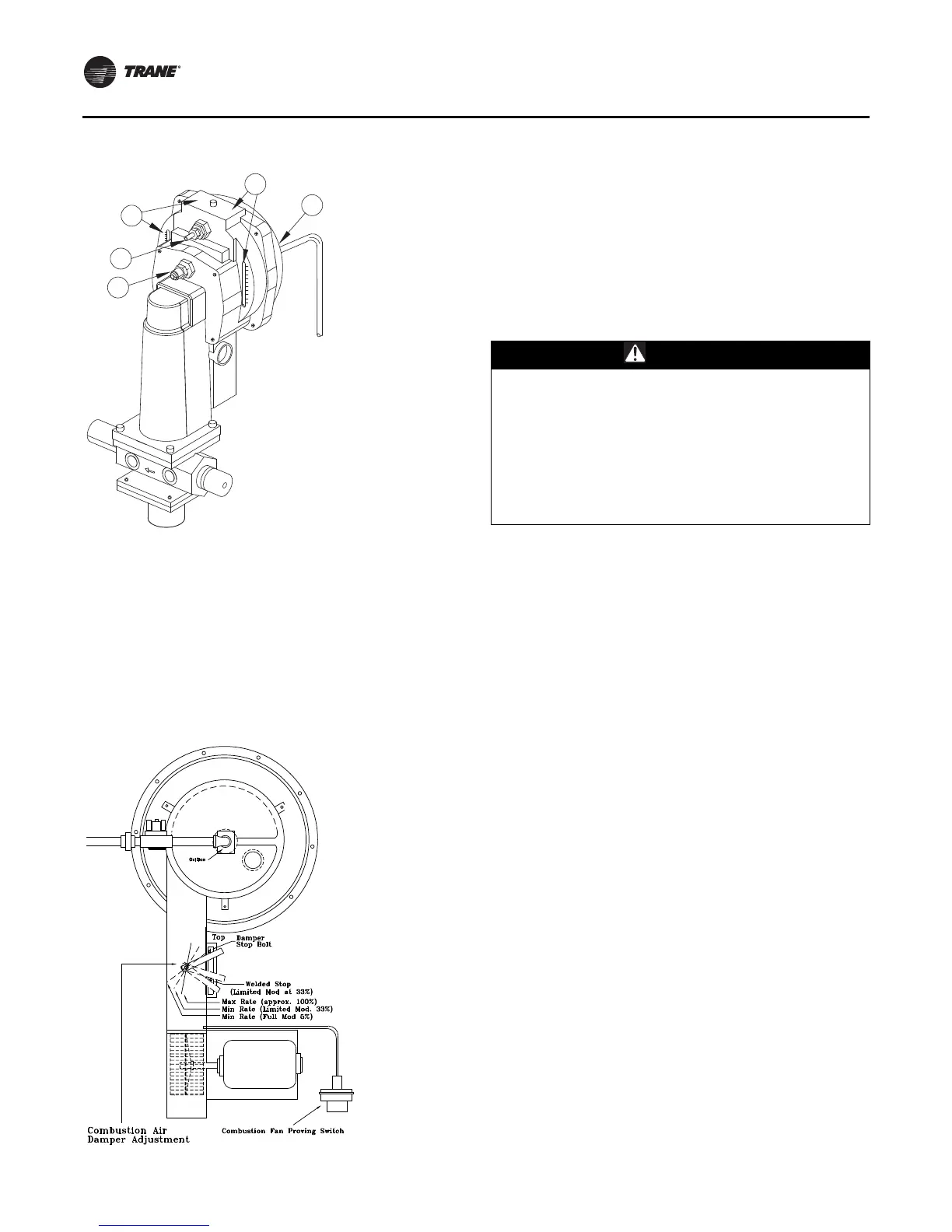
Figure 122. Modulating gas regulator
1. Adjustment and indication of the air to gas ratio.
2. Adjustment and indication of the bias.
3. Connection for the Ambient compensation line.
4. Connection for the gas pressure sensing line.
5. Connection for the air pressure sensing line.
Note: There are no serviceable parts on the SKP70
actuator. Should it become inoperative, replace the
actuator.
Figure 123. Typical gas furnace
1
2
5
3
4
WARNING
Live Electrical Components!
During installation, testing, servicing and
troubleshooting of this product, it may be necessary to
work with live electrical components. Have a qualified
licensed electrician or other individual who has been
properly trained in handling live electrical components
perform these tasks. Failure to follow all electrical
safety precautions when exposed to live electrical
components could result in death or serious injury.