Installation
RT-SVX36K-EN 37
Note: To assure proper condensate flow during
operation, the unit (and curb) must be as level as
possible.The maximum slope allowable for
rooftop unit applications, excluding SSH_'s, is 4"
end-to-end and 2" side-to-side. Units with steam
coils (SSH_'s) must be set level!
If the unit is elevated, a field constructed catwalk around
the unit is strongly recommended to provide easy access
for unit maintenance and service.
Recommendations for installing the SupplyAir and Return
Air ductwork joining the roof curb are included in the curb
instruction booklet. Curb ductwork must be fabricated and
installed by the installing contractor before the unit is set
into place.
Note: For sound consideration, cut only the holes in the
roof deck for the ductwork penetrations. Do not cut
out the entire roof deck within the curb perimeter.
Pitch Pocket Location
The location of the main supply power entry for S_HL 20
through 89Ton rooftop units is located at the bottom right-
hand corner of the control panel.
Figure 14 and Figure 15 illustrate the location for the
electrical entrance through the base in order to enter the
control panel. If the power supply conduit penetrates the
building’s roof beneath this opening, it is recommended
that a pitch pocket be installed before the unit is placed
onto the roof curb.
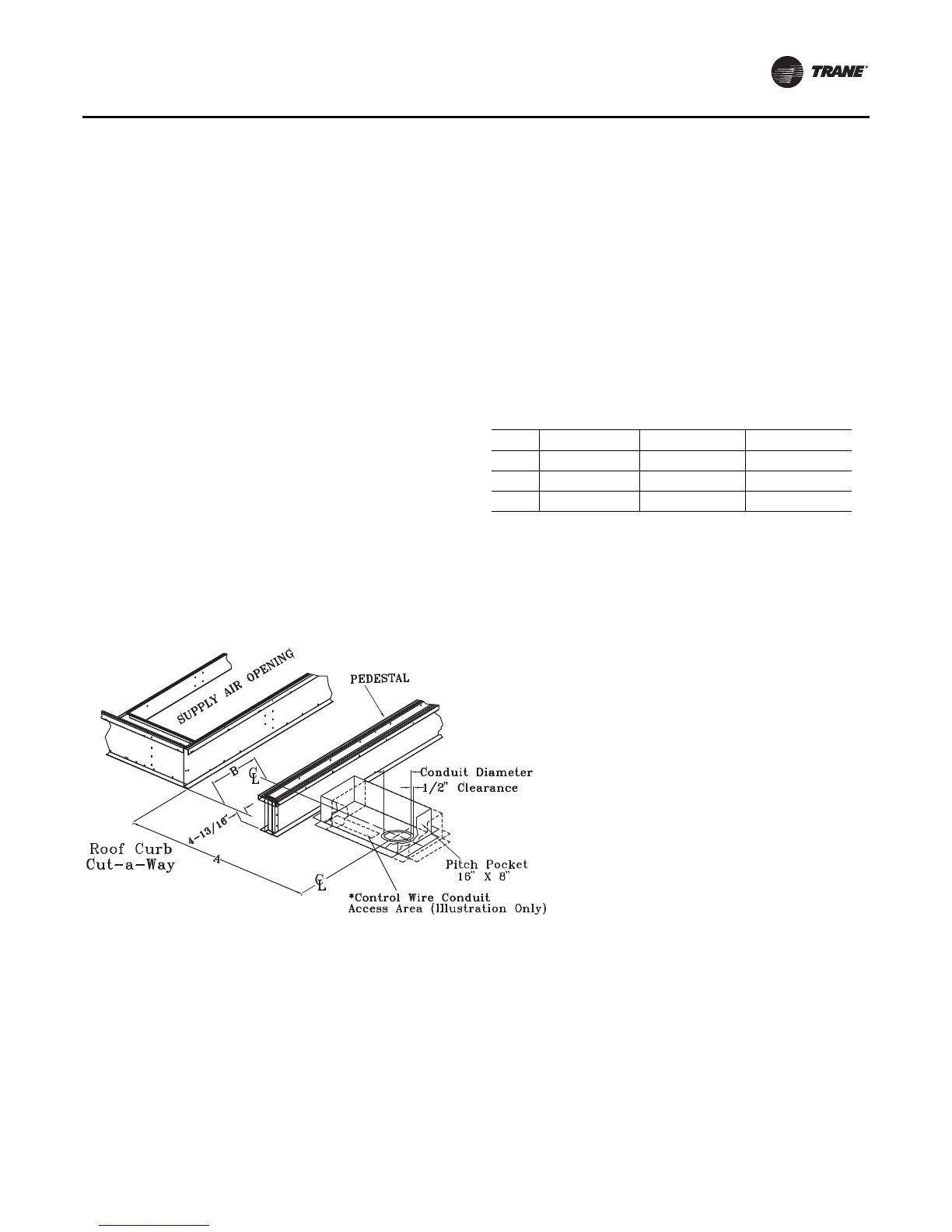
The center line dimensions shown in the illustration below
indicates the center line of the electrical access hole in the
unit base when it is positioned on the curb, ±3/8 inch.The
actual diameter of the hole in the roof should be at least 1/
2 inch larger than the diameter of the conduit penetrating
the roof.This will allow for the clearance variable between
the roof curb rail and the unit base rail illustrated in
Figure 19.
The pitch pocket dimensions listed are recommended to
enhance the application of roofing pitch after the unit is set
into place.The pitch pocket may need to be shifted as
illustrated to prevent interference with the curb pedestal.
If a Trane Curb Accessory Kit is Not Used:
a. The ductwork can be attached directly to the
factory-provided flanges around the unit’s supply
and return air openings. Be sure to use flexible duct
connections at the unit.
b. For “built-up” curbs supplied by others, gaskets
must be installed around the curb perimeter flange
and the supply and return air opening flanges.
Notes:
• If a “built-up” curb is provided by others, keep in mind
that these commercial rooftop units do not have base
pans in the condenser section.
• If this is a REPLACEMENT UNIT keep in mind that the
CURRENT DESIGN commercial rooftop units do not
have base pans in the condenser section.
• Trane roof curbs are recommended. If using a non-
Trane roof curb with right-angle return airflow
approaches to a return fan inlet, a rigid, solid flow
baffle wall should be installed across the full width of
the roof curb return airflow path in the position shown
in Figure 20, p. 38 to reduce potential airflow
Table 16. Pitch pocket dimensions
Unit Tonnage “A” Dimension "B" Dimension
S*HL 20, 25 & 30 4' 5-9/16" 5-9/16"
S*HL 24, 29, & 36 6' 9-11/16” 5-1/2”
S*HL 40 - 89 9' 5-11/16" 5-1/2"
* = All unit functions (SAHL, SEHL, SFHL, SSHL, SLHL and SXHL)
Notes: For design special evaporative-cooled condensing units, please
see the curb installers guide for proper pitch pocket locations.
Figure 19. Pitch pocket location