Installation
RT-SVX36K-EN 51
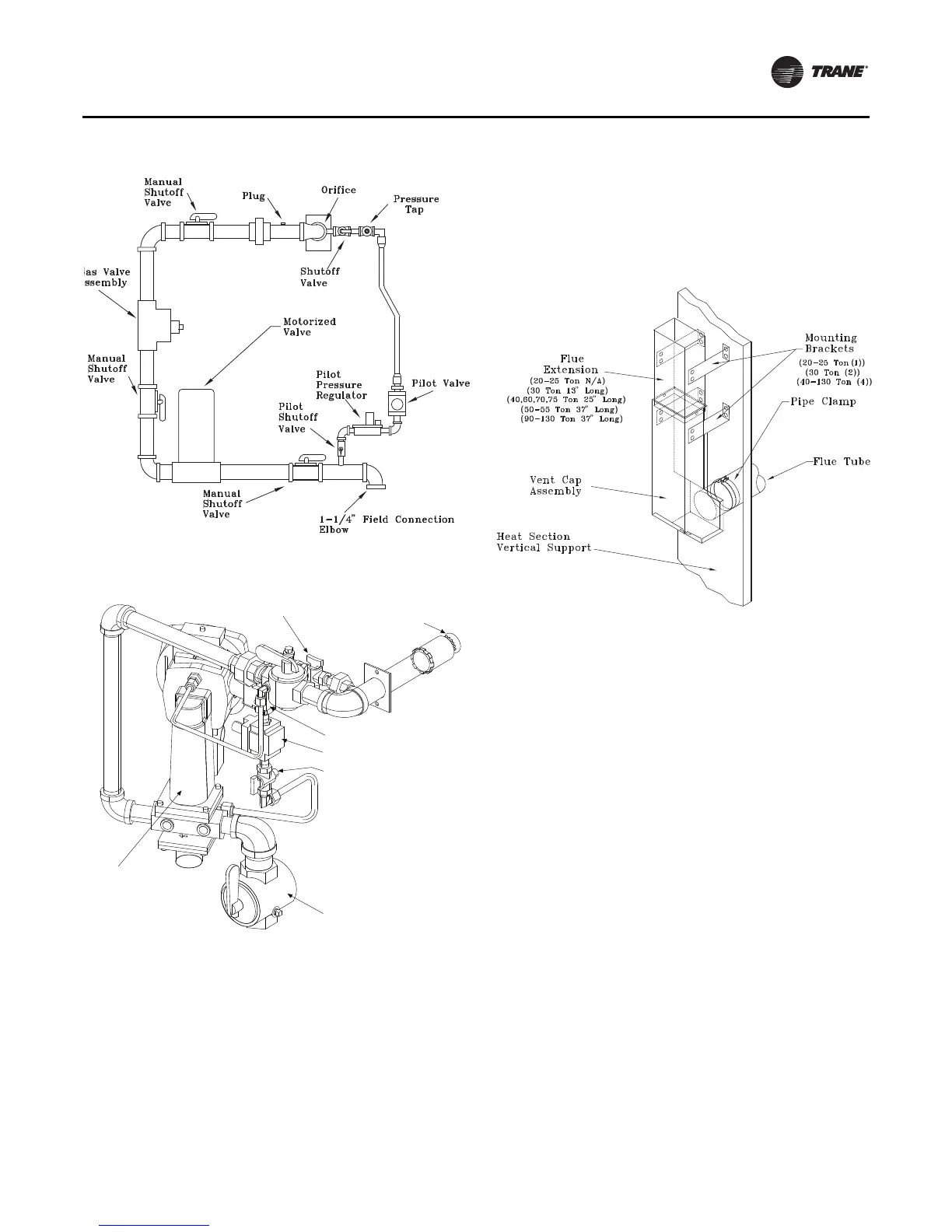
Flue Assembly Installation
1. Locate the flue assembly and the extension (refer to
Figure 34 for extension usage) in the ship with section
of the unit.
2. Install the flue extension onto the flue assembly as
shown in Figure 34.
3. Slide the pipe clamp onto the heater flue tube located
inside the heater compartment.
4. Insert the tube on the flue assembly into the hole
located in the vertical support for the heat section.
5. Butt both flue tube sections together and center the
pipe clamp over joint.
6. Using the pre-punch holes in the flue assembly,
extension, and the vertical support, install the
appropriate number of mounting brackets. Refer to
Figure 34 for details.
Hot Water Heat Units (SLH_)
Hot water heating coils are factory installed inside the
heater section of the unit. Once the unit is set into place,
the hot water piping and the factory provided three way
modulating valve must be installed.The valve can be
installed inside the heat section or near the unit. If the
valve is installed in a remote location, use field supplied
wiring to extend the control wires from the heater section
to the valve.Two access holes are provided in the unit base
as illustrated in Figure 15, p. 29.
Following the guidelines listed below will enhance both
the installation and operation of the “wet heat” system.
Figure 35, p. 53 and Figure 37, p. 54 illustrate the
recommended piping configuration for the hot water coil.
Table 27, p. 62 lists the coil connection sizes.
Note: The valve actuators are not waterproof. Failure to
protect the valve from moisture may result in the
loss of heating control.
1. Support all field-installed piping independently from
the heating coil.
2. Use swing joints or flexible connectors adjacent to the
heating coil. (These devices will absorb the strains of
expansion and contraction).
3. All return lines and fittings must be equal to the
diameter of the “outlet” connection on the hot water
coil.
Figure 32. Unit gas trains (natural gas) 1000 MBH
Figure 33. Modulating 500 - 1000 MBH
Burner Nozzle
Pilot Shutoff Valve
Pilot Solenoid Valve
Pilot Regulator Valve
Pilot Shutoff Valve
Modulating Gas Valve
Shutoff Valve
Figure 34. Flue Assembly

 Loading...


