Unit Replacement
RT-SVX36K-EN 79
Supply and Return Duct Connections
Ensure supply and return duct connections were installed
to the roof curb supply and return areas of roof curb, rather
than to the unit itself.
Remove supply and return duct work if it was directly
connected to the unit.
Lifting procedures
Unit Rigging & Placement
Note: Use spreader bars as shown in Figure 22, p. 39
Refer to the unit Installation, Operation and
Maintenance manual or unit nameplate for the
weight. Refer to the installation instructions
located inside the side control panel for further
rigging information.
A center-of-gravity illustration is shown in Figure 40, p. 57,
dimensional data is shown in Table 12.
Attach adequate strength lifting slings to all four lifting
lugs on 20 through 75Ton units and to all six lifting lugs on
90 through 130Ton units.The minimum distance between
the lifting hook and the top of the unit should be 7 feet for
20 through 75Ton units and 12 feet for 90 through 130Ton
units. Figure 21, p. 39 illustrates the installation of
spreader bars to protect the unit and to facilitate a uniform
lift. Figure 13, p. 35 lists the typical unit operating weights.
Tables 35-37 list weights for previous development
sequences of IntelliPak. (Table numbers will be different in
IOM)
2. Test lift the unit to ensure it is properly rigged and
balanced, make any necessary rigging adjustments.
3. Lift the unit.These units have a continuous base rail
around the air handler section which allows for
placement on dunnage or a tractor trailer for transport.
4. Remove old gasket from the roof curb and place new
gasket material on curb, see Figure 50, p. 81.
Note: See Figure 51, Table 37, p. 82 and Table 38, p. 82 as
well Figure 52, Table 39, p. 83, to determine gasket
material length using roof curb dimensions.
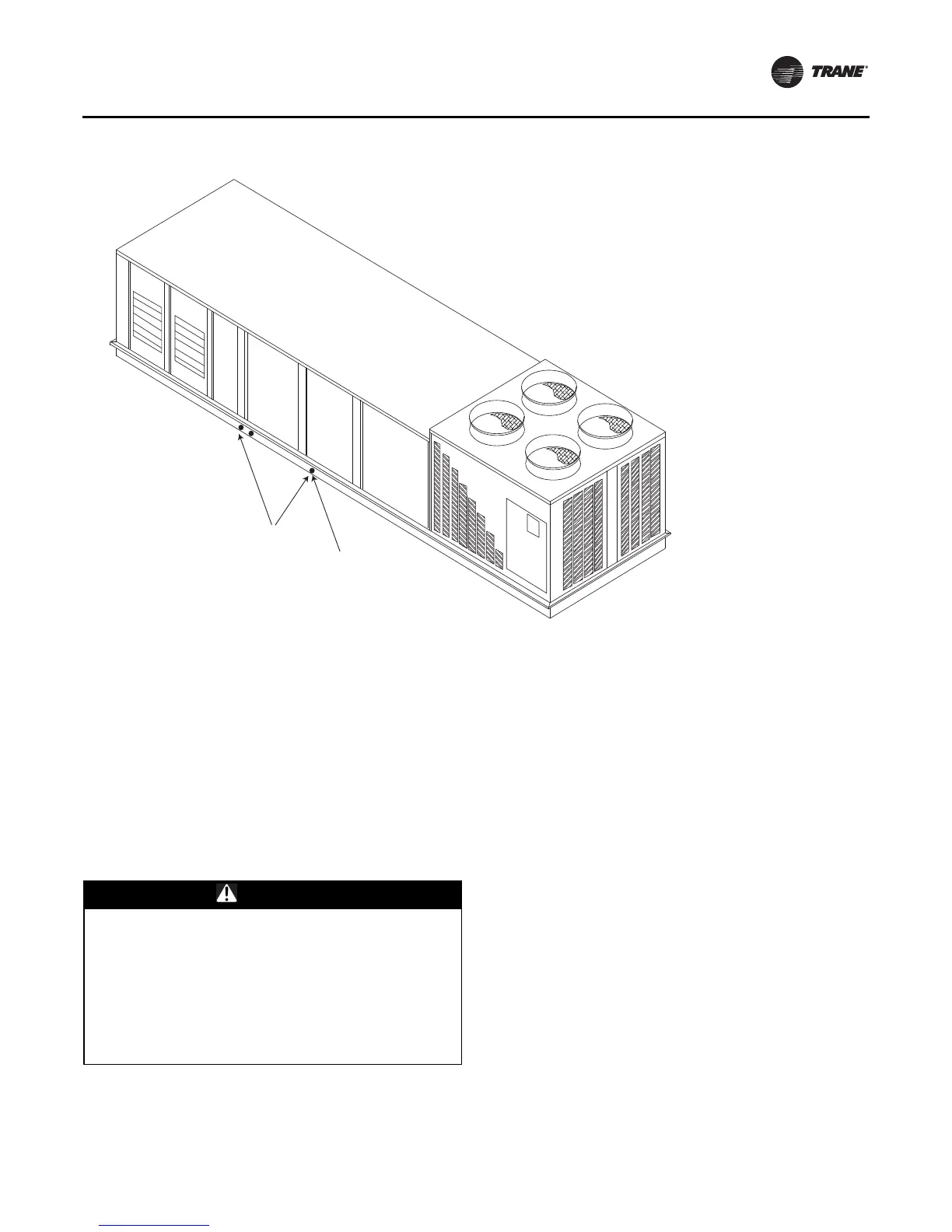
Figure 49. Condensate Drain Locations
Note: Sloped Drain Pan Condensate Drain
Connections When unit has optional sloped drain
pan, connect all 3 drains on each side of the unit
(total 6) to the trapped condensate drain. Each
drain pan connection must be trapped. The
drains may be trapped individually or connected
and then trapped.
Sloped Drain Pan Option
(3) condensate drain
openings both sides
Standard Drain Pan
(1) condensate drain
opening both sides
WARNING
Heavy Objects!
Do not use cables (chains or slings) except as shown.
Each of the cables (chains or slings) used to lift the unit
must be capable of supporting the entire weight of the
unit. Lifting cables (chains or slings) may not be of the
same length. Adjust as necessary for even unit lift.
Other lifting arrangements may cause equipment or
property-only damage. Failure to properly lift unit may
result in death or serious injury. See details below.