Maintenance
RT-SVX36K-EN 171
Fan Belt Adjustment
FC supply fan belts and optional exhaust fan belts must be
inspected periodically to assure proper unit operation.
Optional DDP supply fans do not have belts, and therefore
do not require this maintenance.
Replacement is necessary if the belts appear frayed or
worn. Units with dual belts require a matched set of belts
to ensure equal belt length.
When removing or installing the new belts, do not stretch
them over the sheaves. Loosen the belts using the belt
tension adjustment bolts on the motor mounting base.
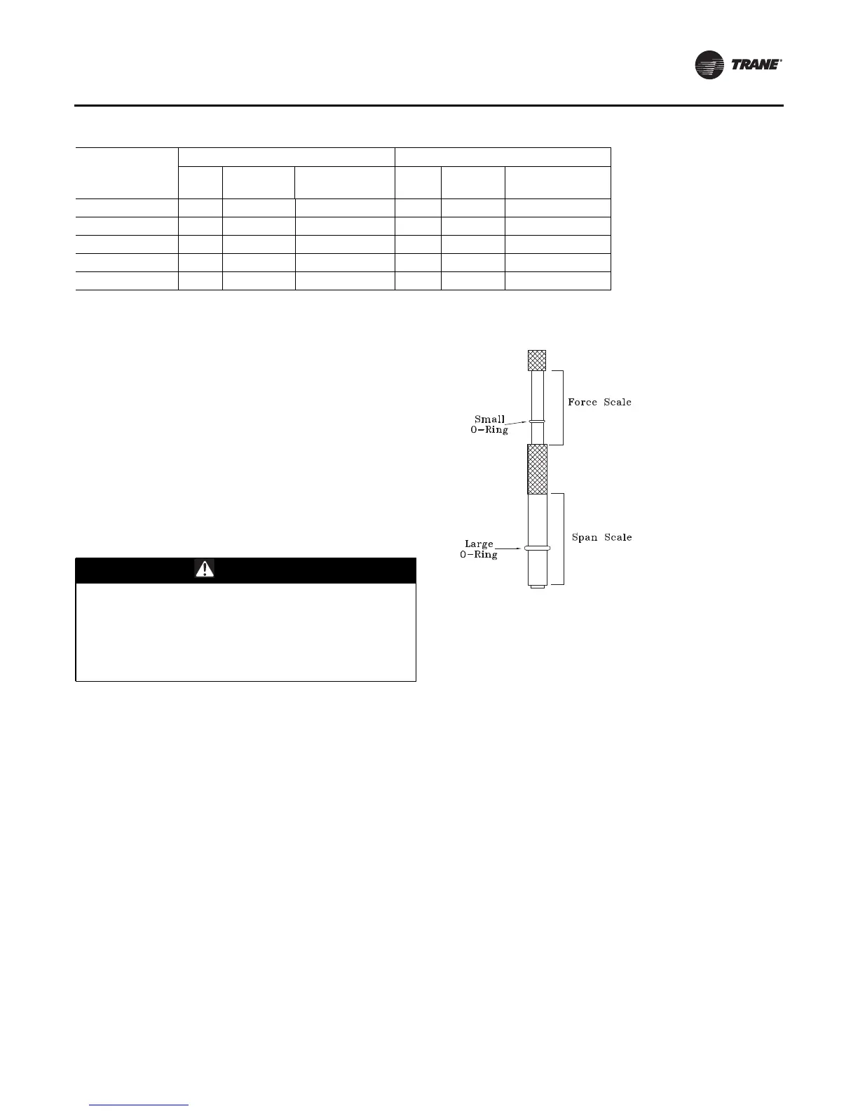
Once the new belts are installed, using a Browning or
Gates tension gauge (or equivalent) illustrated below;
adjust the belt tension as follows:
1. To determine the appropriate belt deflection;
a. Measure the center-to-center shaft distance (in
inches) between the fan and motor sheaves.
b. Divide the distance measured in Step 1a by 64; the
resulting value represents the amount of belt
deflection that corresponds to the proper belt
tension.
2. Set the large O-ring on the belt tension gauge at the
deflection value determined in Step 1b.
3. Set the small O-ring at zero on the force scale of the
gauge plunger.
4. Place the large end of the gauge at the center of the belt
span; then depress the gauge plunger until the large O-
ring is even with the top of the next belt—-or even with
a straightedge placed across the fan and motor
sheaves. Refer to Figure 130.
5. Remove the belt tension gauge.The small O-ring now
indicates a number other than zero on the plunger’s
force scale.This number represents the force (in
pounds) required to give the needed deflection.
6. Compare the “force” scale reading (Step 5) with the
appropriate “force” value listed in Figure 130.Ifthe
“force” reading is outside the range, readjust the belt
tension.
Note: Actual belt deflection “force” must not exceed the
maximum “force” value shown in Figure 130.
7. Recheck the belt tension at least twice during the first
2 to 3 days of operation. Belt tension will decrease
rapidly until the new belts are “run in”.
90 Std 59.3 4/148 1/2 / Enhanced 152 2/276 Microchannel
90 Hi Cap/Hi Eff 59.3 6/148 1/2 / Enhanced 152 2/276 Microchannel
105 Hi 59.3 5/148 1/2 / Enhanced 152 2/276 Microchannel
115 Std 59.3 6/148 1/2 / Enhanced 152 2/276 Microchannel
130 Std 59.3 6/148 1/2 / Enhanced 152 2/276 Microchannel
Table 73. Refrigerant coil fin data (continued)
Evaporator Coil Condenser Coil
Tonnage
Size
(ft2)
Rows/Fin
Series
Tube Diameter/
Surface
Size
(ft2)
Rows/Fin
Series Type
WARNING
Hazardous Voltage!
Disconnect all electric power, including remote
disconnects before servicing. Follow proper lockout/
tagout procedures to ensure the power can not be
inadvertently energized. Failure to disconnect power
before servicing could result in death or serious injury.
Figure 129. Browning (or Gates) tension gauge

 Loading...


