Installation - Mechanical
CLCH-SVX013B-EN 19
To assemble the unit:
1. Locate the mounting hardware and gasket material.
2. All shi
pping supports and crating on the face of the
sections must be removed and discard
ed to permit
proper fit-up and sealing of the surfaces. Remove any
shipping bolts located on the mounting surfaces of the
sections (see Figure 17).
3. Apply the gasketing to one of
the mating surfaces; see
Figure 17, Figure 18, and Figure 19.
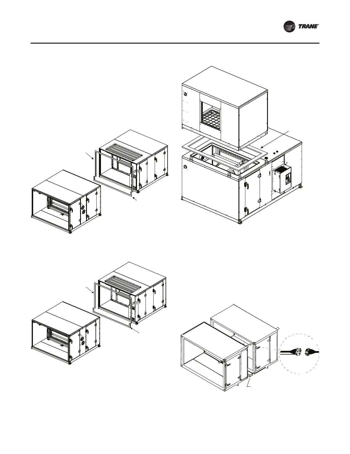
Figure 17. Section-to-section installation
Butyl tape
0.375 in.T x 0.375 in.W
Indoor units
add additional layer of Butyl tape
0.375 in.T x 9.375 in.W
Indoor units - Gasket
Outdoor uits - Butyl tape
Figure 18. Coil section-to-downstream section bolt up
with splash guard
Outdoor units - Butyl tape
0.375 in.T x 0.375 in.W
Indoor units wider than 110 in.
add additional layer of Butyl tape
0.375 in.T x 9.375 in.W
Indoor units - Gasket
Figure 19. Stacked unit assembly
Gasket
X23010544010
1.00 inches T
x
4.00 inches W
4. If the unit is equipped with factory-mounted controls,
move adjacent subassembly within six inches and
fasten quick connects where the sections bolt together.
See Figure 20 for low voltage. See Figure 21 and
Figure 22 for high voltage.
Note: Re
ference the appropriate controller manual for
more details on the installation of units with
factory-mounted controls.
Figure 20. Horizontal section-to-section low voltage
quick connects
Use 2 x 4 inch wood to protect
hands from accidental pinching
Low voltage