54
RT-SVX092A-EN
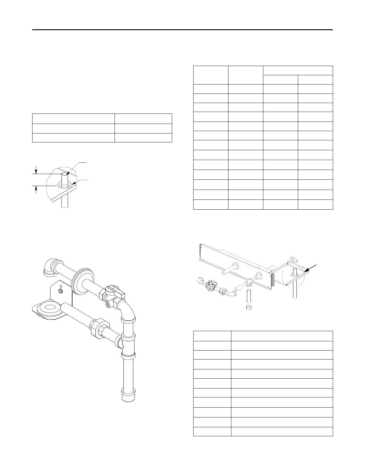
cap from the base pan opening. See Figure 76, p. 54
and Figure 77, p. 54.
3. Route field piping through this hole to the dimension
shown in Table 9, p. 54.
4. Place the assembly through the cabinet opening shown
in Figure 77, p. 54 and Figure 78, p. 54, and make the
union connection to the field piping and to the gas train.
Table 9. Through-the-base gas piping dimension
Cabinet
Dimension A (inch)
A.0, B.0, and C.0
4 5/8
D.0 and D.1 1 3/16
Figure 76. Through-the-base gas pipe height
A
Customer Gas Supply Pipe
Grommet
DETAIL A
Figure 77. Through-the-base gas pipe assemblies for
A.0, B.0, and C.0 cabinet units
A
B
C
D
A
E
F
G
H
J
K
L
M
I
1/2-in. and 3/4-in., Gas Pipe Connection
Table 10. Through-the-base gas pipe assembly
components for A.0, B.0 and C.0 cabinets
Component Description
Connection Size
1/2 inch 3/4 inch
A Grommets ½ ¾
B TBUG bracket - -
C 90° Elbow ½ ¾
D
Pipe fitting
½ x 7¼ ¾ x 6½
E Gas ball valve ½ ¾
F Street elbow ½ ¾
G
Pipe fitting
½ x 2 ½ ¾ x 2¼
H
Tee pipe
½ ¾
I
Pipe fitting
½ x 4 ¾ x 4
J
Pipe cap
½ ¾
K
Pipe fitting
½ x 2 ¾ ¾ x 2
L
Pipe union
½ ¾
M
Pipe fitting
½ x 4 ½ ¾ x 5¼
Note: All modulating gas models use 3/4-inch gas piping.
Figure 78. Through-the-base gas pipe assembly for
D.0 and D.1 cabinets
See Detail A
A
B
C
D
E
M
L
K
J
I
H
F
N
O
G
Table 11. Through-the-base gas pipe assembly for
D.0 and D.1 cabinets
Component Description
A Grommet
B Grommet
C
Pipe Fitting (3/4-in. x 8 1/2-in.)
D 90° Elbow
E
Support Plate
F Tee
G
Pipe Fitting (3/4-in. x 4-in.)
H
Cap
I
Pipe Fitting (3/4-in. x 2 1/2-in.)
J 90° Street Elbow
Installation