Installation Electrical
RTHD-SVX02H-EN 67
D
WARNING
Hazardous Voltage!
Disconnect all electric power, including remote dis-
connects and discharge all motor start/run capacitors
before servicing. Follow proper lockout/tagout pro-
cedures to ensure the power cannot be inadvertently
energized. Verify with an appropriate voltmeter that
all capacitors have discharged. Failure to disconnect
power and discharge capacitors before servicing could
result in death or serious injury.
6. If the “CBA” indicator glows instead, open the unit
main power disconnect and switch two line leads on
the line power terminal block (or the unit mounted
disconnect). Reclose the main power disconnect and
recheck phasing.
7. Reopen the unit disconnect and disconnect the phase
indicator.
Terminal Lugs
Proper starter/control panel line-side lug sizes are spec-
ified on the starter submittals. These lug sizes must be
compatible with conductor sizes specified by the elec-
trical engineer or contractor. Appropriate lug sizes are
provided.
Circuit Breakers and Non-Fused Disconnect
Switches (factory installed Option)
Units that are ordered with factory installed Circuit
Breakers or Non-Fused Disconnect Switches ship with
the handle in the control panel. The handle must be in-
stalled prior to starting the unit.
The operating mechanism is already pre installed on the
Disconnect/ Circuit Breaker frame.
The hole locations and shafts lengths have already been
cut. And the shaft already installed.
D
WARNING
Hazardous Voltage!
Disconnect all electric power, including remote dis-
connects and discharge all motor start/run capacitors
before servicing. Follow proper lockout/tagout pro-
cedures to ensure the power cannot be inadvertently
energized. Verify with an appropriate voltmeter that
all capacitors have discharged. Failure to disconnect
power and discharge capacitors before servicing could
result in death or serious injury.
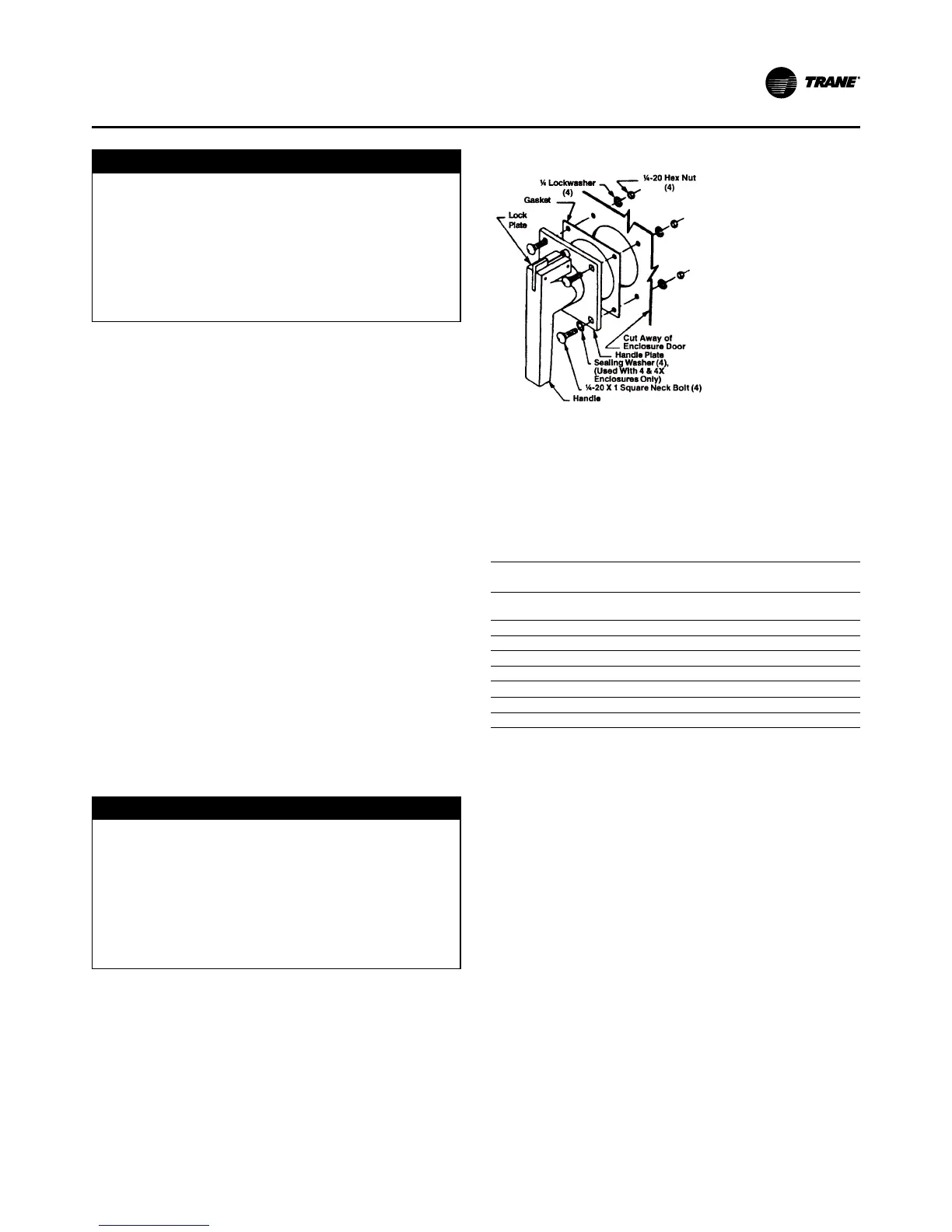
1. Attach the handel and gasket to the enclosure door
and secure with the four bolts, lock washers and nut
as shown in Figure 33. Tighten to 75 in-Lbs.
Note: There is an additional lexan spacer on the handel
not shown in the Figure 33, do not remove.
Figure 33. Handle on Door
2. Check that when the enclosure door is closed, the
handle interlocks with the shaft in all handel posi-
tions except RESET/OPEN. To open the enclosure
door when the breaker is in the ON position, rotate
the screw slot on the handle plate counter -clockwise.
Verify operation.
Table 19. Lug Sizes
RLA Circuit Breaker Non-fused
Disconnect Switch
1-185 (2) 2/0 - 250 MCM or
(1)2/0 - 500
(1) #4 - 350 MCM
186-296 (2) 2/0 - 250 MCM or 2/0 - 500
297-444 (2) 3/0 - 350 MCM
445-592 (2) 1 - 500 MCM
593-888 (4) 4/0 - 500 MCM
RLA Main Lugs Only
1-623 (2) #4-500 MCM
624-888 (4) #4/0-500 MCM
Fused Disconnect Switches
Size fused disconnects in accordance with NEC Article
440-22(a).
Rated Load Amperage (RLA)
The compressor motor RLA for a particular chiller is de-
termined by the field selection program and indicated on
the compressor nameplate.
Minimum Circuit Ampacity (MCA)
The MCA is equal to 1.25 x the compressor RLA (on
nameplate).
Maximum Fuse/Circuit Breaker Size
The maximum fuse/circuit breaker size is equal to 2.25 x
the compressor RLA in accordance with UL 1995, para.
36.15.See also NEC 440-22.
The recommended dual element (RDE) fuse size is equal
to 1.75 x RLA in accordance with NEC Table 430-152.
For recommended field connection lug sizes (RTHD start-
ers) see Table 19.