RLC-SVX09Q-EN
33
lead to poor efficiency, poor oil management and possible
freeze-up of evaporator.
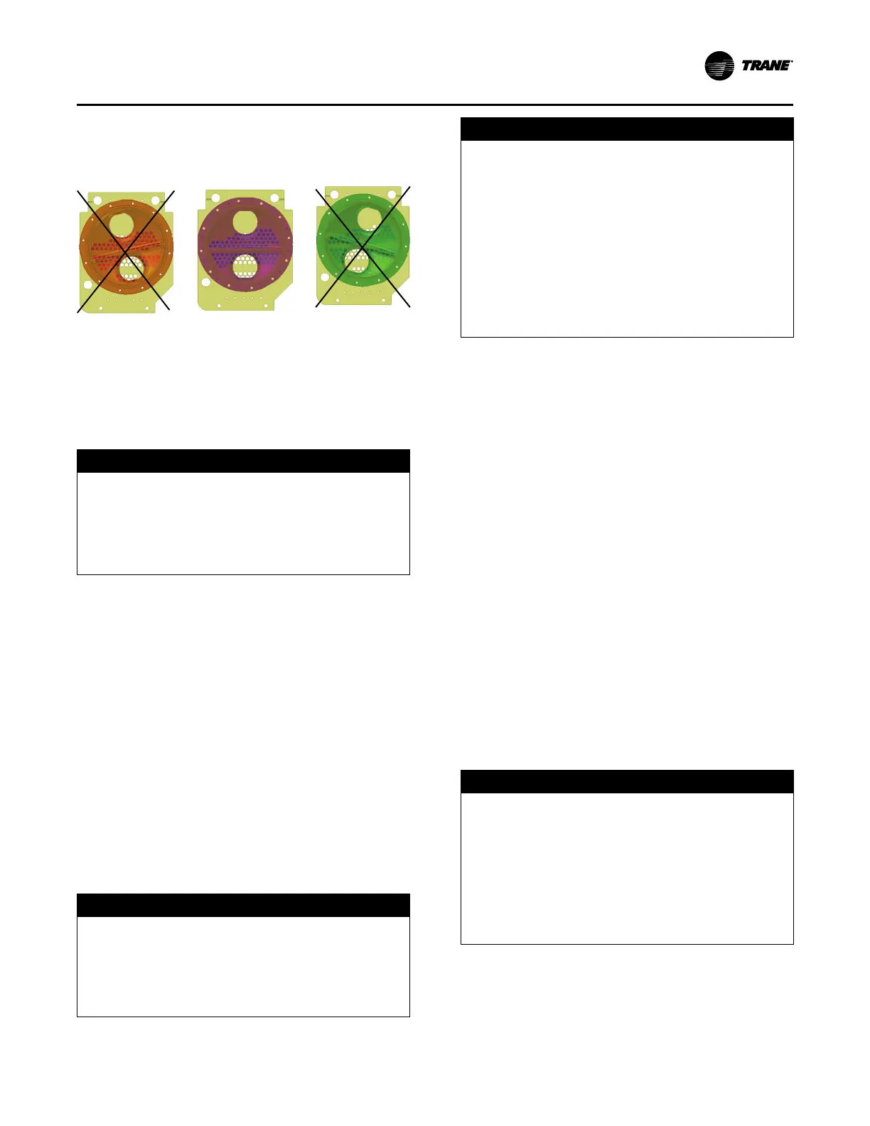
Figure 16. RTWD waterboxes
Evaporator Piping Components
Piping components include all devices and controls used to
provide proper water system operation and unit operating
safety. These components and their general locations are
given below.
Drain and Vents
NOTICE
Waterbox Damage!
Failure to follow instructions could result in damage
to the waterbox.
Do not over-tighten or use excessive Teflon® pipe
tape when installing valves, drains, plugs and vents
on waterboxes.
Drains and vents are located on each evaporator waterbox.
When the unit is shipped, the drain plugs are removed and
placed in a plastic bag in the control panel, along with the
condenser drain plugs. Each drain and vent must be piped
with a shutoff valve, or plug reinstalled, prior to water pump
operation.
Entering Chilled Water Piping - Field
Installed
• Air vents (to bleed air from system)
• Water pressure gauges with shutoff valves
• Vibration eliminators
• Shutoff (isolation) valves
• Thermometers (if desired)
• Cleanout tees
• Relief valve
• Pipe strainer
NOTICE
Water Borne Debris!
To prevent components damage, pipe strainers must
be installed in the water supplies to protect
components from water borne debris. Trane is not
responsible for equipment-only-damage caused by
water borne debris.
NOTICE
Evaporator Damage!
Failure to follow instructions below could cause
damage to the evaporator.
The chilled water connections to the evaporator are to
be grooved-pipe type connections. Do not attempt to
weld these connections, as the heat generated from
welding can cause microscopic and macroscopic
fractures on the cast iron waterboxes that can lead to
premature failure of the waterbox. To prevent damage
to chilled water components, do not allow evaporator
pressure (maximum working pressure) to exceed 150
psig (10.5 bar).
Leaving Chilled Water Piping - Field Installed
• Air vents (to bleed air from system)
• Water pressure gauges with shutoff valves
• Vibration eliminators
• Shutoff (isolation) valves
• Thermometers
• Cleanout tees
• Balancing valve
• Flow Switch (not required if factory installed flow switch
option is selected)
Evaporator Flow Switch (Optional)
If factory installed flow switch option is selected, switch is
programmed based on the operating conditions submitted
with the order. The leaving evaporator temperature, fluid
type and fluid concentration affect the selected flow switch.
If the operating conditions on the job site change, the flow
switch may need to be replaced.
The flow switch is powered with 24 Vac. Indicators on
switch are as follows:
• Green - power is applied
• Amber - always off
NOTICE
Proper Water Treatment Required!
The use of untreated or improperly treated water
could result in scaling, erosion, corrosion, algae or
slime.
Use the services of a qualified water treatment
specialist to determine what water treatment, if any, is
required. Trane assumes no responsibility for
equipment failures which result from untreated or
improperly treated water, or saline or brackish water.
Important: If using an acidic commercial flushing solution,
construct a temporary bypass around the unit
to prevent damage to internal components of
the evaporator and condenser.
Installation - Mechanical