RLC-SVX09Q-EN
47
To provide proper phasing of 3-phase input, make
connections as shown in field wiring diagrams and as
stated on the WARNING label on the starter panel. For
additional information on proper phasing, refer to Unit
Voltage Phasing. Proper equipment ground must be
provided to each ground connection in the panel (one for
each customer-supplied conductor per phase). 115 volt
field-provided connections (either control or power) are
made through knockouts on the right side of the panel. See
the following figure. Additional grounds may be required for
each 115 volt power supply to the unit. A terminal strip is
provided for 115V customer wiring.
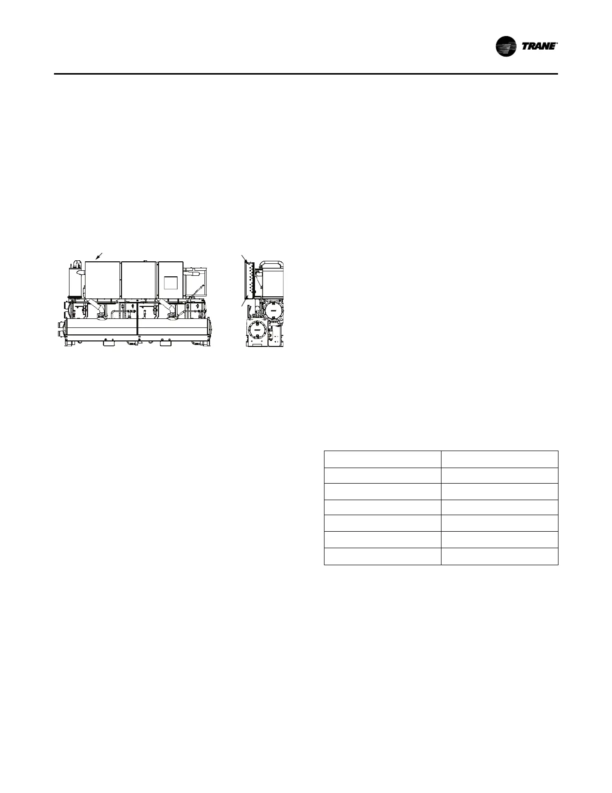
Figure 25. Power entrance
Low
Voltage
Entrance
(lower)
High
Voltage
Entrance
(Upper)
Incoming
Power Entrance
Control Power Supply
The unit is equipped with a control power transformer.
Additional control power voltage to the unit is not
necessary. No other loads should be connected to the
control power transformer.
All units are factory-connected for appropriate labeled
voltages.
Interconnecting Wiring
Chilled Water Flow (Pump) Interlock
If factory installed flow switch option is not selected, RTWD
Series R
®
chillers require a field-supplied control voltage
contact input through a flow proving switch 5S5 and an
auxiliary contact 5K9 AUX. Connect the proving switch and
auxiliary contact to 1A15 J3-1 and 1X4-1. Refer to the field
wiring for details. The auxiliary contact can be BAS signal,
starter contactor auxiliary, or any signal which indicates the
pump is running. A flow switch is still required and cannot
be omitted.
Condenser Water Flow Interlock
If factory installed flow switch option is not selected, RTWD
Series R
®
chillers require a field-supplied control voltage
contact input through a flow proving switch 5S6 and an
auxiliary contact 5K10 AUX. Connect the proving switch
and auxiliary contact to 1A15 J2-1 and 1X4-1. Refer to the
field wiring for details. The auxiliary contact can be BAS
signal, starter contactor auxiliary, or any signal which
indicates the pump is running. A flow switch is still required
and cannot be omitted.
Chilled Water Pump Control
If factory installed flow switch option is not selected, RTWD
Series R
®
chillers require a field-supplied control voltage
contact input through a flow proving switch 5S6 and an
auxiliary contact 5K10 AUX. Connect the proving switch
and auxiliary contact to 1A15 J2-1 and 1X4-1. Refer to the
field wiring for details. The auxiliary contact can be BAS
signal, starter contactor auxiliary, or any signal which
indicates the pump is running. A flow switch is still required
and cannot be omitted.
The relay output from board 1A14 is required to operate the
Evaporator Water Pump (EWP) contactor. Contacts should
be compatible with 115/240 Vac control circuit. The EWP
relay operates in different modes depending on chiller
control or Tracer commands, if available, or service
pumpdown. (See maintenance section). Normally, the
EWP relay follows the AUTO mode of the chiller. Whenever
the chiller has no diagnostics and is in the AUTO mode,
regardless of where the auto command is coming from, the
normally open relay is energized. When the chiller exits the
AUTO mode, the relay is timed open for an adjustable
(using Tracer
®
TU) 0 to 30 minutes. The non- AUTO
modes in which the pump is stopped, include Reset, Stop,
External Stop, Remote Display Stop, Stopped by Tracer,
Low Ambient Run Inhibit, and Ice Building complete.
Regardless of whether the chiller is allowed to control the
pump on a full-time basis, if the MP calls for a pump to start
and water does not flow, the evaporator may be damaged
catastrophically. It is the responsibility of the installing
contractor and/or the customer to confirm that a pump will
start when called upon by the chiller controls.
Table 17. Pump relay operation
Chiller Mode Relay Operation
Auto Instant close
Ice Building Instant close
Tracer Override Close
Stop Timed Open
Ice Complete Instant Open
Diagnostics Instant Open
Note: Exceptions are listed below.
When going from Stop to Auto, the EWP relay is energized
immediately. If evaporator water flow is not established in 4
minutes and 15 sec., the chiller control de-energizes the
EWP relay and generates a non-latching diagnostic. If flow
returns (e.g. someone else is controlling the pump), the
diagnostic is cleared, the EWP is re-energized, and normal
control resumed.
If evaporator water flow is lost once it had been
established, the EWP relay remains energized and a
nonlatching diagnostic is generated. If flow returns, the
diagnostic is cleared and the chiller returns to normal
operation.
Installation - Electrical