34
RLC-SVX09Q-EN
Dirt, scale, products of corrosion, and other foreign material
will adversely affect heat transfer between the water and
system components. Foreign matter in the chilled water
system can also increase pressure drop and, consequently,
reduce water flow. Proper water treatment must be
determined locally, depending on the type of system and
local water characteristics.
Neither salt nor brackish water is recommended for use in
Trane air-cooled Series R® chillers. Use of either will lead
to a shortened life to an indeterminable degree. Trane
Technologies encourages to have a reputable water
treatment specialist, familiar with local water conditions, to
assist in this determination and in the establishment of a
proper water treatment program.
Using untreated or improperly treated water in these units
may result in inefficient operation and possible tube
damage. Consult a qualified water treatment specialist to
determine whether treatment is needed.
Indexing Flow Switch
To properly index the flow switch, the following
requirements must be met:
• The dot must be at a position no greater than 90° off
Index.
• The torque must be between 22 ft-lb minimum and 74
ft-lb maximum.
• A minimum distance of 5x pipe diameter must be
maintained between flow switch and any bends, valves,
changes in cross sections, etc.
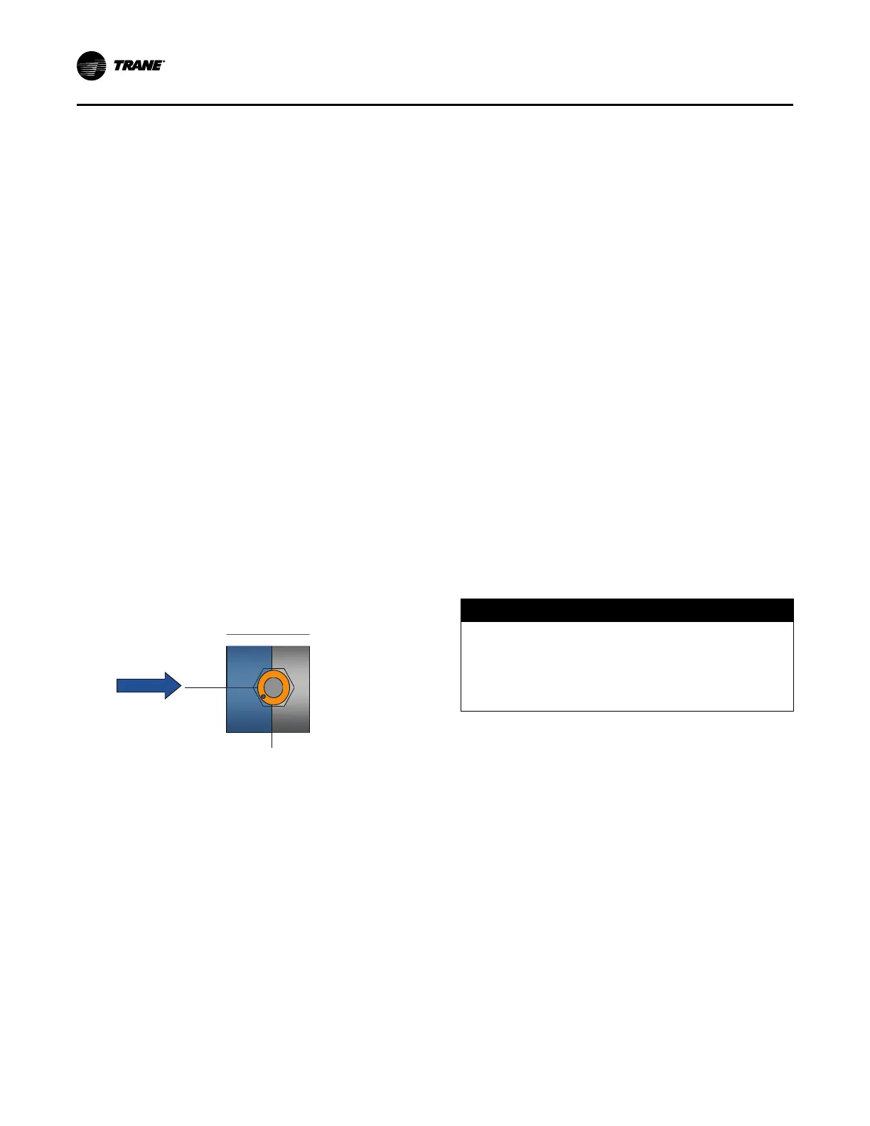
Figure 17. Proper flow switch indexing
Flow
Top View
Index
The flow switch must have the dot in the shaded area
to the left of this line for proper indexing (±90° off Index)
Flow Proving Devices
Important: If factory installed flow switch option is not
selected, installer must provide flow switches
or differential pressure switches with pump
interlocks to prove water flow.
To provide chiller protection, install and wire flow switches
in series with the water pump interlocks, for both chilled
water and condenser water circuits. See Installation
Electrical chapter. Specific connections and schematic
wiring diagrams are shipped with the unit.
Flow switches must prevent or stop compressor operation
if system water flow falls below the required minimum
shown on the pressure drop curves. Follow the
manufacturer’s recommendations for selection and
installation procedures. General guidelines for flow switch
installation are outlined below.
• Mount the switch upright, with straight horizontal runs
on either side. The length of the horizontal runs should
be a minimum of 5 pipe diameters.
• Do not install close to elbows, orifices, or valves.
Note: The arrow on switch must point in direction of
water flow.
• To prevent switch fluttering, remove all air from water
system.
Note: Chiller control provides a 6-sec time delay on
flow switch input before shutting down unit on
loss-of-flow diagnostic. Contact a qualified
service organization if the machine shutdown
persists.
• Adjust switch to open when water flow falls below
minimum required. See “General Data,” p. 9 tables for
minimum flow recommendations. Flow switch is closed
on proof of water flow.
NOTICE
Evaporator Damage!
Failure to follow instructions could result in
evaporator damage.
To prevent evaporator damage, do not use water flow
switch to cycle the system.
Pressure Drop Curves
For overlapping pressure drop curves, see “General
Data,” p. 9 tables for limit values.
Installation - Mechanical