56
RLC-SVX09Q-EN
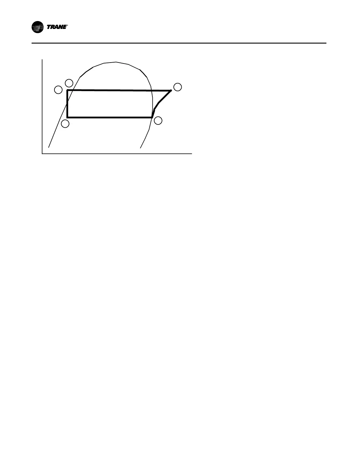
Figure 29. Pressure enthalpy curve
Pressure
Enthalpy
Liquid
1
3
5
2
4
Evaporation of refrigerant occurs in the evaporator. A
metered amount of refrigerant liquid enters a distribution
system in the evaporator shell and is then distributed to the
tubes in the evaporator tube bundle. The refrigerant
absorbs heat and vaporizes as it cools the water flowing
through the evaporator tubes. Refrigerant leaves the
evaporator as saturated vapor (State Pt. 1).
The refrigerant vapor generated in the evaporator flows to
the suction end of the compressor where it enters the
motor compartment of the suction-gas-cooled motor. The
refrigerant flows across the motor, providing the necessary
cooling, then enters the compression chamber. Refrigerant
is compressed in the compressor to discharge pressure
conditions. Simultaneously, lubricant is injected into the
compressor for two purposes: (1) to lubricate the rolling
element bearings, and (2) to seal the very small clearances
between the compressor’s twin rotors. Immediately
following the compression process the lubricant and
refrigerant are effectively divided using an oil separator.
The oil-free refrigerant vapor enters the condenser at State
Pt. 2. The lubrication and oil management issues are
discussed in more detail in the compressor description and
oil management sections that follow.
A discharge baffle within the condenser shell distributes the
compressed refrigerant vapor evenly across the condenser
tube bundle. Cooling tower water, circulating through the
condenser tubes, absorbs heat from this refrigerant and
condenses it.
As the refrigerant enters the bottom of the condenser
(State Pt. 3), it enters an integral subcooler where
additional heat is removed before traveling to the electronic
expansion valve (State Pt. 4). The pressure drop created
by the expansion process vaporizes a portion of the liquid
refrigerant. The resulting mixture of liquid and gaseous
refrigerant then enters the Evaporator Distribution system
(State Pt. 5). The flash gas from the expansion process is
internally routed to compressor suction, while the liquid
refrigerant is distributed over the tube bundle in the
evaporator.
The chiller maximizes the evaporator heat transfer
performance while minimizing refrigerant charge
requirements. This is accomplished by metering the liquid
refrigerant flow to the evaporator’s distribution system
using the electronic expansion valve. A relatively low liquid
level is maintained in the evaporator shell, which contains a
bit of surplus refrigerant liquid and accumulated lubricant. A
liquid level measurement device monitors this level and
provides feedback information to the unit controller, which
commands the electronic expansion valve to reposition
when necessary. If the refrigerant level rises, the expansion
valve is closed slightly, and if the level is dropping, the
valve is opened slightly such that a steady level is
maintained.
Compressor
A two-pole, hermetic, induction motor (3600 rpm at 60 hz,
3000 rpm at 50hz) directly drives the compressor rotors.
The motor is cooled by suction refrigerant gas from the
evaporator as it is routed back to the compressor rotors.
Oil Management
The unit is configured with an oil management system to
confirm proper oil circulation throughout the unit. The key
components of the system include an oil separator, oil filter,
oil sump, and oil sump heater. An auxiliary oil cooler is
installed when the chiller is purchased as a high
condensing temperature or low evaporator temperature
unit.
Operating Principles