RLC-SVX09Q-EN
45
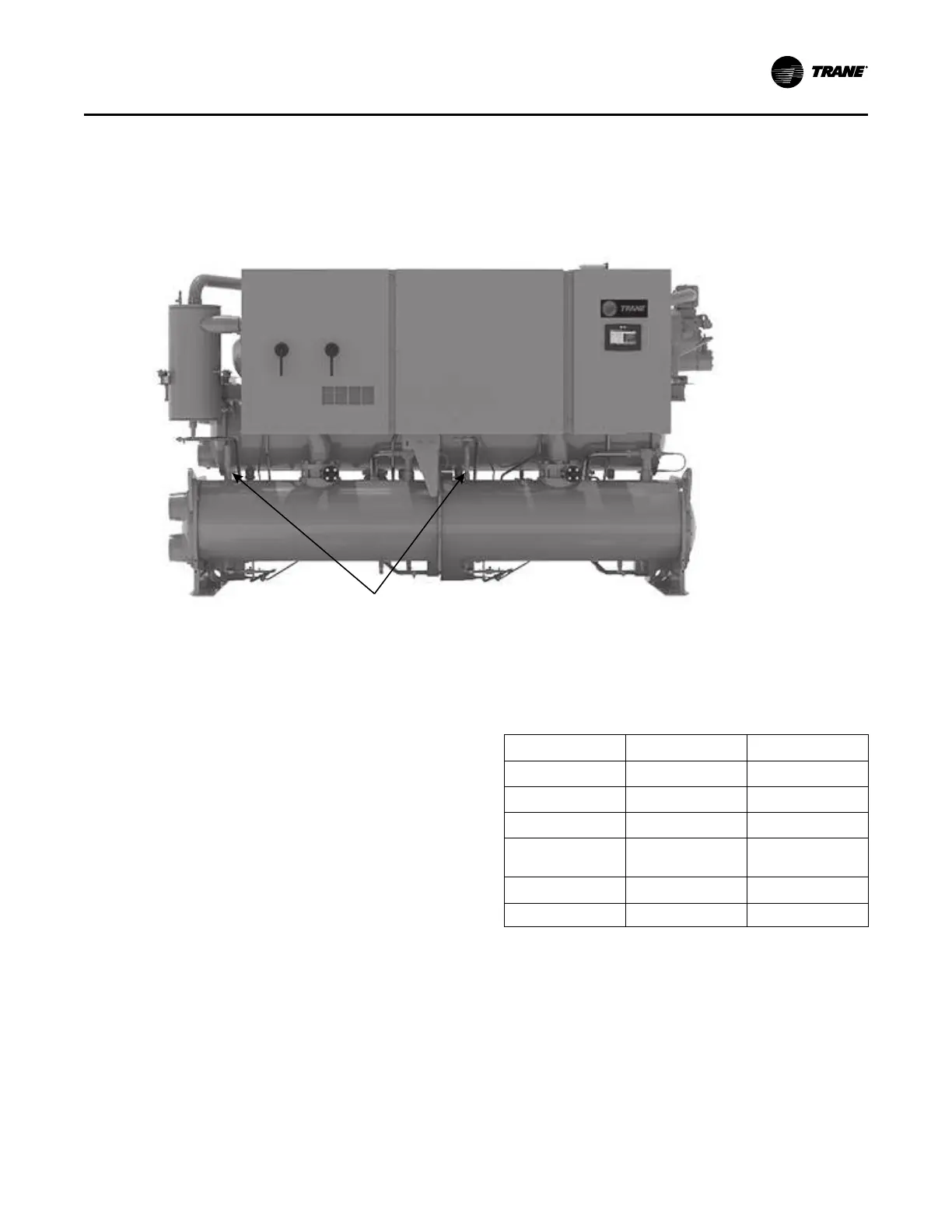
Figure 24. Evaporator relief valves
Note: Vent line length must not exceed code
recommendations. If the line length will exceed code
recommendations for the outlet size of the valve,
install a vent line of the next larger pipe size.
Low side relief valve discharge setpoints are 200 psig.
Once the relief valve has opened, it will re-close when
pressure is reduced to a safe level.
Pipe each relief valve on the unit into a common vent line.
Provide an access valve located at the low point of the vent
piping, to enable draining of any condensate that may
accumulate in the piping.
Summary of Relief Valves
Table 16. Relief valve descriptions
Condenser Evaporator
Units High Pressure Side Low Pressure Side
Relief Setpoint 300 psig 200 psig
Quantity (standard) 1 per ckt 1 per ckt
Quantity (Dual Relief
Valves option)
2 per ckt 2 per ckt
Relief Rate (lb/min) 25.4 28.9
Filed Connection Size 5/8 in. MFL 3/4 in. NPTFI
Installation - Mechanical