RLC-SVX09Q-EN
55
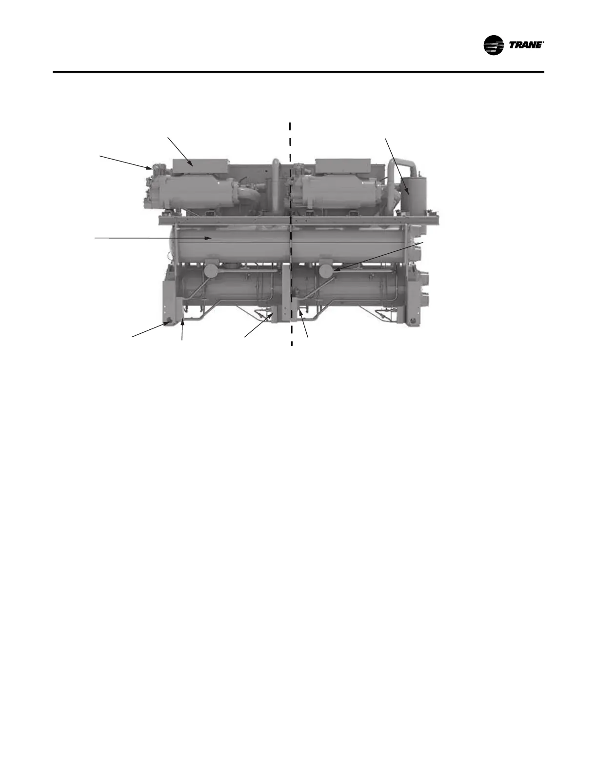
Figure 28. RTWD components – back view
Circuit 1
Circuit 2
Oil Separator
Refrigerant
Filter
Liquid Level
Sensor
Thermosyphon
BPHE
Oil Cooler
2-inch Pipe Stabilizer Hole
Condenser
ASME
Nameplate
Discharge
Service Valve
Compressor
Junction Box
Refrigeration (Cooling) Cycle
Overview
The refrigeration cycle of the Series R
®
chiller is
conceptually similar to that of other Trane chiller products.
It makes use of a shell-and-tube evaporator design with
refrigerant evaporating on the shell side and water flowing
inside tubes having enhanced surfaces.
The compressor is a twin-rotor helical rotary type. It uses a
suction gas-cooled motor that operates at lower motor
temperatures under continuous full and part load operating
conditions. An oil management system provides an almost
oil-free refrigerant to the shells to maximize heat transfer
performance, while providing lubrication and rotor sealing
to the compressor. The lubrication system confirms long
compressor life and contributes to quiet operation.
Refrigerant is condensed in a shell-and- tube heat
exchanger where refrigerant is condensed on the shell side
and water flows internally in the tubes.
Refrigerant is metered through the flow system using an
electronic expansion valve, that maximizes chiller
efficiency at part load.
A unit-mounted starter and control panel is provided on
every chiller. Microprocessor-based unit control modules
provide for accurate chilled water control as well as
monitoring, protection and adaptive limit functions. The
adaptive nature of the controls intelligently prevents the
chiller from operating outside of its limits, or compensates
for unusual operating conditions, while keeping the chiller
running rather than simply tripping due to a safety concern.
When problems do occur, diagnostic messages assist the
operator in troubleshooting.
Cycle Description
The refrigeration cycle for the RTWD chiller can be
described using the pressure-enthalpy diagram shown
below. Key State Points are indicated on the figure and are
referenced in the discussion following.
Operating Principles