RLC-SVX19G-GB
156
4 UNT-PRC002-GB
Technical Data
FWD 08 12 20 30 45
Power supply (V/Ph/Hz) 230/1/50
Capacities
Cooling capacity on water (1) (kW) 5,2 8,3 15 18,8 30,1
Heating capacity on water (2) (kW) 6,3 11,9 18,9 20,9 38,2
Fan motor (type) 2 x direct drive centrifugal
Fan power input (3) (kW) 0,23 0,46 0,65 1,04 1,51
Current amps (3) (A) 1,1 2,2 3,1 4,7 5,5
Start-up amps (A) 3,2 5,5 9,3 14,1 16,5
Air flow
minimum (m
3
/h) 490 980 1400 1800 2700
nominal (m
3
/h) 820 1650 2300 3000 4500
maximum (m
3
/h) 980 1970 2600 3600 5400
Main coil
Water entering/leaving connections (type) ISO R7 rotating female
(Dia) 3/4" 3/4" 1 1/2" 1 1/2" 1 1/2"
Electric heater (accessory for blower only)
Electric power supply (V/Ph/Hz) 230/1/50 230/1/50 or 400/3/50 400/3/50 400/3/50 400/3/50
Heating capacity (kW) 2/4 8 10 12 12
Hot water coil (accessory for blower only)
Heating capacity (4) (kW) 6,3 12 17,4 22,4 34,5
G2 filter (filter box accessory)
Quantity 2 2 2 2 2
Dimensions ( LxWxth) (mm) 386x221x8 486x271x8 586x321x8 586*421*8 586*621*8
G4 filter (filter box accessory)
Quantity - 2 2 2 2
Dimensions ( LxWxth) (mm) - 486x264x48 586x314x48 586*414*48 586*614*48
Condensate pump (accessory) (type) Centrifugal
Water flow - lift height (l/h - mm) 24 - 500
Not available for FWD30 and FWD45
Sound level (L/M/H speed)
Sound pressure level (5) (dB(A)) 36/40/43 38/41/44 46/50/53 47/52/57 47/52/58
Sound power level (5) (dB(A)) 46/50/53 48/51/54 56/60/63 57/62/67 57/62/68
Unit dimensions
Width x Depth (mm) 890 x 600 1090 x 710 1290 x 820 1290 x 970 1290 x 1090
Height (mm) 250 300 350 450 650
Shipped unit dimensions
Width x Depth (mm) 933 x 644 1133 x 754 1333 x 864 1333 x 1008 1333*1133
Height (mm) 260 310 360 460 660
Weight (kg) 32 46 61 76 118
Colour galvanised steel
Recommended fuse size
Unit alone (aM/gI) (A) 8/16 8/16 8/16 8/25 8/25
Unit with electric heater (gI) (A) 16 (2kW),25 (4kW) 40 (230V),3*16 (400V) 3*20 3*25 3*25
(1) Conditions: Water entering/leaving temperature: 7/12 °C, Air inlet temperature 27/19°C DB/WB - Nominal air flow
(2) Conditions: Water entering/leaving temperature: 50/45 °C, Air inlet temperature 20°C DB - Nominal air flow
(3) At high speed with nominal air flow.
(4) Water entering/leaving temperature 90/70 °C, air inlet temperature 20 °C DB, Nominal air flow.
(5) A rectangular glass wool duct 1m50 long is placed on the blower.The measurement is taken in the room containing the blower unit.
Heat exchanger operating limits:
FWD:
*water temperature: max 100° C
*absolute service pressure: min 1 bar/max 11 bars
Accessories - Hot water coil:
*water temperature: min. +2° C/max. 100° C
*absolute service pressure: min 1 bar/max 11 bars
Operating Principles
Refrigerant Circuit
Each unit has two refrigerant circuits, with one or
two rotary screw per circuit. Each refrigerant circuit
includes a compressor suction and discharge service
valve, liquid line shutoff valve, removable core filter,
liquid line sight glass with moisture indicator, charging
port and electronic expansion valve. Fully modulating
compressors and electronic expansion valve provide
variable capacity modulation over the entire operating
range.
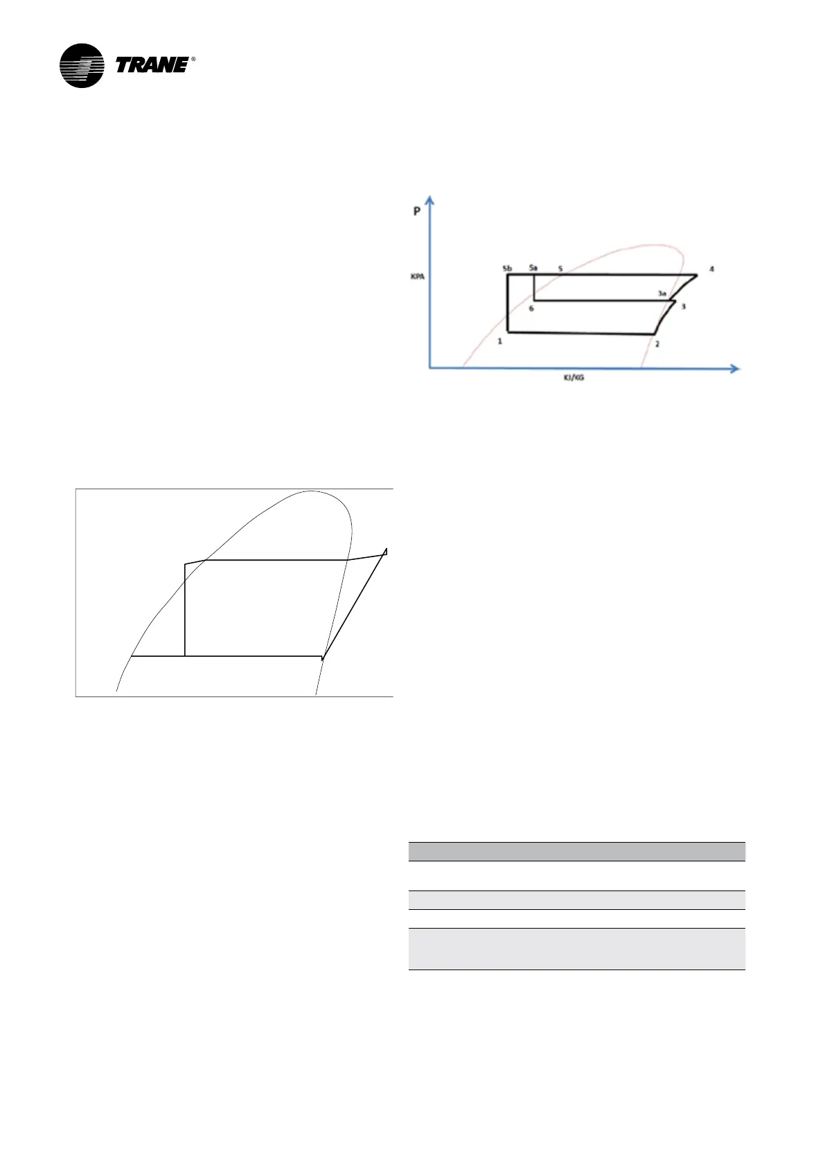
Refrigerant Cycle
Typical refrigerant cycle on the RTAF is represented
on the pressure enthalpy diagram shown in the figure
below. Key state points are indicated on the figure. The
cycle for the full load design point is represented in the
plot.
Figure 34 – Pressure enthalpy (P-h) diagram
The RTAF chiller uses a shell and tube evaporator design
with refrigerant evaporating on the shell side and water
flowing inside tubes having enhanced surfaces (states
4 to 1). The suction lines are designed to minimize
pressure drop (states 1 to 1b) the compressor is a twin-
rotor helical rotary compressor designed similarly to the
compressors offered in other Trane screw compressor
based chiller (states 1b to 2). The discharge lines include
a highly efficient oil separation system that removes
99,8% of the oil from the refrigerant stream going to
the heat exchangers (states 2 to 2b). De-superheating,
condensing and sub-cooling are accomplished in a
microchannel cooled heat exchanger where refrigerant
is condensed inside the microchannel (states 2b to 3b).
Refrigerant flow through the system is balanced by an
electronic expansion valve (states 3b to 4).
Refrigerant Cycle with Economizer
Liquid refrigerant either leaves the micro channel
condenser at point 5a and a part of it flows to the
secondary expansion valve and enters BPHE economizer
at point 6 and then the flow is vaporized to the
compressor economizer port at state 3a. Meanwhile
the major part flows to BPHE economizer acting as
an additive subcooler and refrigerant is cooled down
to state 5b then the major part of the liquid flow goes
through the main expansion valve and returns to the
evaporator at state 1.
Refrigerant and Oil
RTAF use R134a, R513A or R1234ze, Trane believes that
responsible refrigerant practices are important to the
environment, our customers, and the air conditioning
industry. All technicians who handle refrigerants must be
properly qualified. All local and UE regulations in what
handling, reclaiming, recovering and recycling, must be
followed.
R134a/R513A/R1234ze is a medium pressure refrigerant.
It may not be used in any condition that would cause
the chiller to operate in vacuum without a purge system.
RTAF is not equipped with a purge system. Therefore
RTAF must not be operated in a condition that would
result in a saturated condition in the chiller of -26°C or
lower. R134a/R513A/R1234ze requires the use of specific
POE oils as designated on the unit nameplate and listed
on the table 31.
Table 31 – Trane oil according to refrigerant
Refrigerant Trane OIL
R134a & R513 xed
speed compr
OIL0048E/OIL0023E
R513A OIL0048E/OIL0023E
R134a+R513 with VFD OIL00317/OIL00315
R1234ze OIL00317/OIL00315
OIL066E/OIL067E possible if on
nameplate
KJ/kg
1
1b
2
3
3b
4

 Loading...
